en

Need Help Now? Call Us!
+86-159 9623 5291

Our team proudly offers an on-time guarantee and a 100% customer satisfaction guarantee.
Contact Online


 Home / News / Industry News / How Does a Solenoid Directional Valve Work? Step-by-Step Operation Guide
  2026.09.23
  Industry News
 Content
A maintenance technician testing a tractor's three-point hitch often hears a click but sees no movement. That click is the solenoid coil energizing. The problem is either coil voltage, a stuck spool, or a blocked pilot port. The reason a spool moves, or does not, starts with one principle used in every solenoid directional valve: an electrical current generates a magnetic force that physically shifts a hydraulic spool.
A solenoid directional valve works by energizing a coil to create an electromagnetic field, which exerts a linear magnetic force on an armature that is mechanically linked to a spool. When the armature moves, the spool shifts to a new position and connects different hydraulic ports, reversing the flow path to a cylinder or motor.
The mechanism is direct and repeatable:
This entire cycle happens in 30 to 100 ms, depending on oil viscosity, coil power, and spool travel distance. The electrical command can come from a simple switch or from a machine controller, which makes remote control of hydraulic flow a practical option for how a solenoid directional valve controls hydraulic flow in closed-loop systems.
A solenoid directional valve works by energizing a coil to create an electromagnetic field, which exerts a linear magnetic force on an armature that is mechanically linked to a spool.
The number of ports and the number of positions define what a solenoid directional valve can do in a hydraulic circuit. Ports are threaded or flange connections where lines attach. The four ports in a standard 4-way valve are P (pump), T (tank), A (work port 1), and B (work port 2). Positions are the distinct spool locations. A 2-position valve shifts between two states. A 3-position valve has a middle neutral state where the spool can be sprung to center.
| Configuration | Ports | Positions | Typical function |
| 4/3 | 4 (P, T, A, B) | 3 | Extend, hold, retract on a double-acting cylinder |
| 4/2 | 4 (P, T, A, B) | 2 | Reverse flow direction between two actuator lines |
| 3/2 | 3 (P, T, A) | 2 | Switch flow on and off to a single actuator line |
| 2/2 | 2 (P, A) | 2 | Open or close a single flow path |
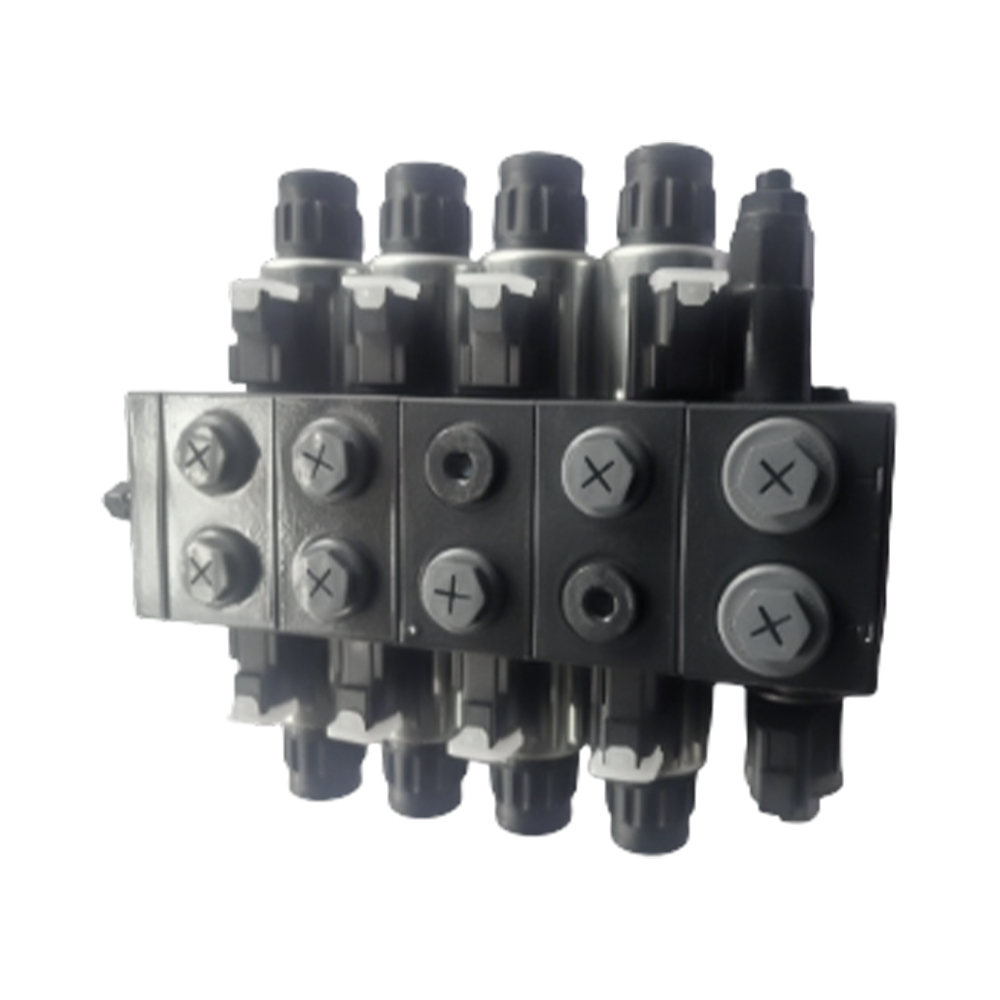 4-Way Hydraulic Solenoid Directional Valve with Modular DesignThe PDCF50 is a 4-way solenoid valve offering robust construction and reliable switching. Its modular design allows flexible integration, aiding precise actuator control and minimizing pressure loss in demanding hydraulic systems.View Product →
The neutral position in a 3-position valve is critical. In open-center, P connects to T while A and B are blocked. In closed-center, all four ports are blocked. This affects system standby pressure and actuator holding behavior.
A direct-acting solenoid valve uses the full coil force to move the main spool. A pilot-operated valve uses a small solenoid to control a tiny pilot spool, which then draws system pressure to shift the larger main spool.
The decision between direct acting and pilot operated usually comes down to flow rate and available electrical power. For a 40 L/min tractor lift circuit, a direct acting valve is normally sufficient. For a 200 L/min combine harvester hydraulic system, a pilot operated valve is more practical because it avoids a large, power-hungry coil.
A wet pin solenoid design means the armature is immersed in hydraulic oil inside the solenoid tube, and this improves heat transfer and lubrication compared to a dry pin design. The oil in the solenoid tube absorbs heat from the coil and carries it through the valve body to the housing. This prevents thermal degradation of the coil insulation. The oil also lubricates the armature, reducing friction and mechanical wear during repeated shifting cycles.
For agricultural and construction machinery, where duty cycles can reach 30 to 50 percent, the wet pin design is a practical reliability feature. Dry pin solenoids are still used in simpler circuits, but they tend to overheat when energized continuously. The design choice directly affects the expected service life of the valve in a demanding application.
A wet pin solenoid design keeps the armature immersed in oil, improving heat dissipation and extending the life of the valve in high-duty-cycle circuits.
The selection process starts with the circuit requirements, not the valve catalog. First, determine the required flow rate in L/min. Second, define the working pressure, typically 250 to 350 bar in mobile hydraulics. Third, choose the valve function and spool type based on actuator behavior. Fourth, match the coil voltage and connector. Fifth, confirm the mounting style and port size.
A useful checklist for selecting the right directional control valve includes these eight factors:
Solenoid directional valves are the primary automation interface in mobile hydraulic circuits, and agriculture is where their advantages show up most clearly. In a tractor's three-point hitch, a solenoid directional valve controls the raise and lower cylinder when the operator presses a switch. In a combine harvester, the same type of valve adjusts reel speed and header positioning. In construction machines, it routes oil to boom, arm, and bucket cylinders.
The common thread is that these valves let the operator control hydraulic flow with a small electrical signal, which is easier than running mechanical linkages to every valve. This becomes especially important in modern machinery where the operator is already switching controls near the cab.
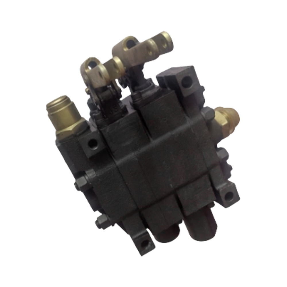
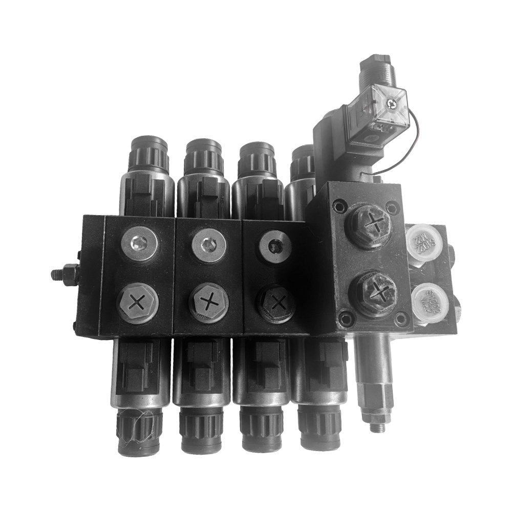 Solenoid Valve for Tractor Hydraulic Lift ControlThis electrically controlled valve is built for tractor lift systems, enabling rapid and smooth directional switching. It provides dependable operation for raising, lowering, and floating implements in agricultural machinery.View Product →
A solenoid directional valve is a switching valve. It moves the spool to discrete positions and cannot throttle the flow continuously. A proportional directional valve applies a variable current to the coil, which positions the spool at any point between its limits, enabling flow and direction control with full precision. Switching valves are simpler and cheaper; proportional valves are used where smooth acceleration and fine metering are required.
The most common causes are no voltage at the coil, an open coil, a stuck spool due to contamination, or insufficient pilot pressure in a pilot-operated valve. Check the electrical supply first, then inspect the valve for debris and confirm that the return spring is intact.
Yes, but the duty cycle depends on the solenoid design. Wet pin solenoids handle continuous energization better than dry pin solenoids because the oil immersion improves heat dissipation. Review the manufacturer's duty cycle rating at the intended working pressure before finalizing the design.
12 V and 24 V DC are most common in mobile equipment. Industrial valves often use 110 V or 220 V AC. The coil must match the vehicle's electrical system. 12 V systems are more common in agriculture because of the vehicle's existing wiring.
Recommended Products

Contact Info.
+86-159 9623 5291
No. 5, Chuangye Road, Niandou Industrial Park, Ma'anshan City, Anhui Province, China
MOBILE QR CODE

 English
  Español