en
Need Help Now? Call Us!
+86-159 9623 5291

Our team proudly offers an on-time guarantee and a 100% customer satisfaction guarantee.
Contact Online


 Home / News / Industry News / How to Select the Right Directional Control Valve for Hydraulic Systems?
  2026.04.03
  Industry News
 Content
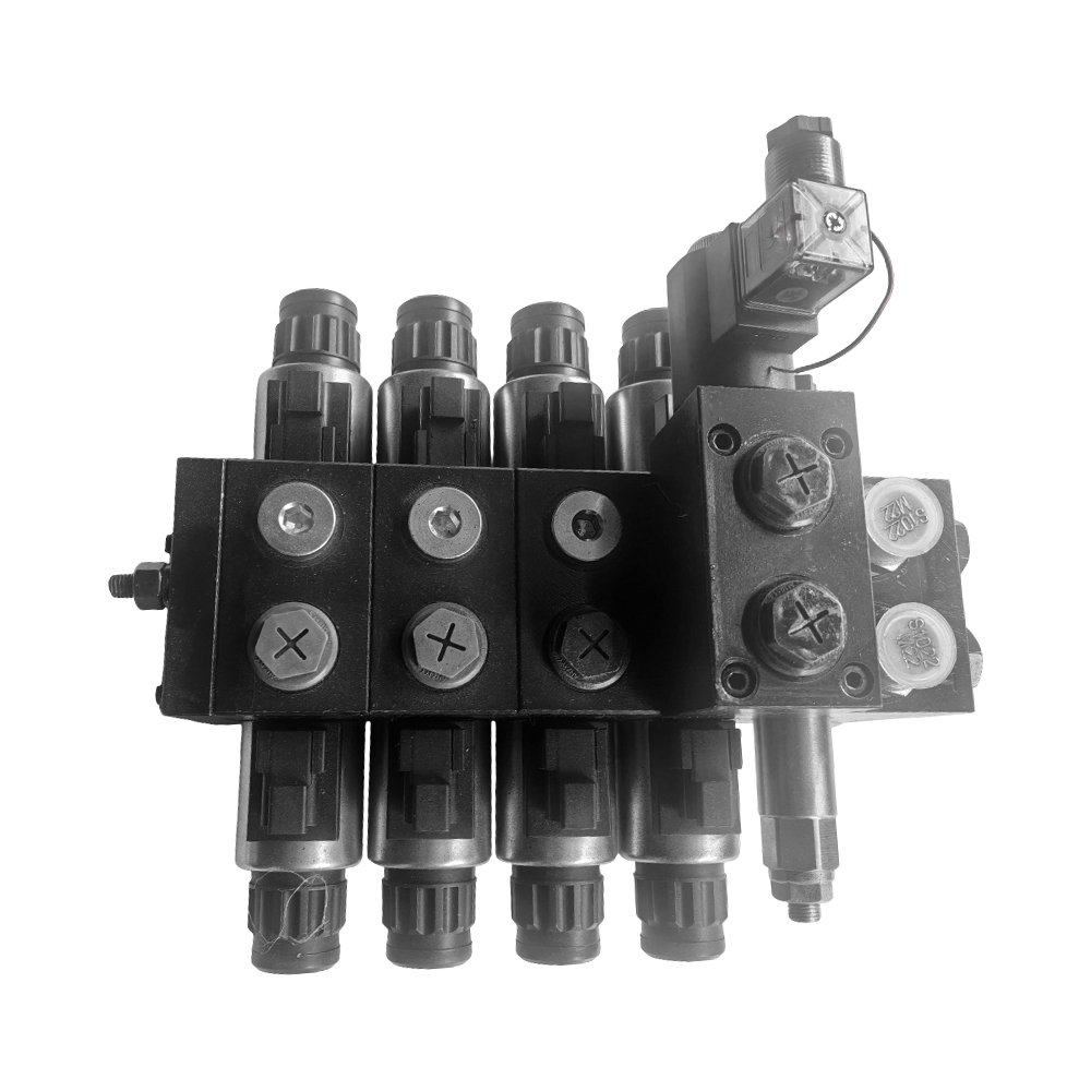
Selecting a hydraulic component can be a complex task for engineers and procurement specialists. The Directional Control Valve serves as the core component for managing fluid flow and actuator movement. This guide provides a technical deep dive into valve selection, performance characteristics, and application-specific considerations to support B2B buyers and system designers.
A Directional Control Valve manages the start, stop, and direction of fluid flow within a hydraulic circuit. These valves are defined by their number of ports and spool positions. For industrial machinery, the reliability of this component directly impacts system efficiency and safety. Engineers must evaluate flow rate, pressure rating, and actuation method to ensure compatibility with the overall system architecture.
When researching components, buyers often focus on specific configurations. The following high-search-volume terms represent common procurement and design needs in the hydraulic industry.
Engineers classify hydraulic directional control valve types based on construction, spool design, and operation method. Each category serves distinct applications, from mobile equipment to industrial presses. Understanding these differences helps in selecting the correct component for specific flow and pressure requirements.
Manual valves use a lever or cam to shift the spool directly. Pilot-operated valves use hydraulic pressure to move the main spool, allowing for remote control and higher flow rates. The choice depends on the required control precision and system complexity.
Direct-acting valves shift fully when energized or actuated. Proportional valves provide variable spool positioning, enabling controlled acceleration and deceleration of actuators. The proportional directional control valve working principle involves a solenoid that adjusts the spool position based on input current, offering precise flow control for complex motion applications.
The spool is the heart of the valve. Its design defines the flow path and overlap characteristics. Directional control valve spool types include open center, closed center, tandem center, and float center configurations. Each spool type affects system behavior during neutral conditions.
Open center spools allow fluid to flow back to the tank when the valve is neutral, which is common in mobile machinery to reduce energy consumption. Closed center spools block flow in neutral, maintaining pressure for downstream circuits. Tandem center spools combine features, enabling motor or cylinder operation with specific neutral flow paths.
The table below summarizes the characteristics of common spool types used in industrial and mobile applications.
| Spool Type | Neutral Flow Path | Typical Application |
|---|---|---|
| Open Center | Flow to tank | Tractors, loaders, agricultural equipment |
| Closed Center | Flow blocked | Industrial presses, high-pressure systems |
| Tandem Center | Pump to tank, actuator ports blocked | Mobile cranes, hydraulic lifts |
| Float Center | All ports connected to the tank | Grapples, implements requiring free movement |
Hydraulic schematics use standardized symbols to represent valve functions. Access to a directional control valve symbols PDF is essential for system design and troubleshooting. Each symbol indicates the number of ports, positions, and flow paths. For example, a 4/3 valve symbol shows four ports and three positions, with each square representing a switching state. Understanding these diagrams ensures correct installation and maintenance procedures.
Proportional valves bridge the gap between simple on/off controls and complex servo systems. The proportional directional control valve working principle relies on a proportional solenoid that applies force proportional to the electrical input. This force moves the spool against a spring, creating a variable orifice. System feedback, often from a position transducer, allows precise metering of flow. These valves are critical in applications requiring smooth acceleration, such as injection molding machines and material handling equipment.
System downtime often relates to valve performance issues. A structured directional control valve troubleshooting guide helps engineers diagnose failures efficiently. Common problems include spool sticking due to contamination, seal leakage, and solenoid failure.
For systematic diagnosis, engineers should measure pressure at the valve ports, verify electrical signals, and inspect the fluid condition. Regular sampling and preventive maintenance extend valve life significantly.
When sourcing a Directional Control Valve, procurement and engineering teams must align technical specifications with operational demands. Key parameters include maximum flow rate, pressure rating, actuation type, and mounting interface (subplate or manifold). Certifications such as CE or ISO 9001 manufacturing standards also influence supplier selection. Additionally, evaluating the availability of replacement parts and technical support reduces long-term operational risks.
A Directional Control Valve determines the path of fluid flow—typically changing the direction of an actuator—while a flow control valve regulates the flow rate (speed) of the fluid. In a hydraulic circuit, both work together to achieve precise movement and velocity control.
Symbols follow ISO 1219 standards. Each square represents a valve position. Lines within squares indicate flow connections. Numbers or letters around the symbol identify ports (P = pressure, T = tank, A/B = actuator). A directional control valve symbols PDF from a technical library provides a comprehensive reference for all configurations.
Sticking is usually caused by fluid contamination, mechanical misalignment, or thermal expansion. Contaminants like metal particles or degraded seal material can lodge in the spool clearance. Flushing the system and replacing filters often resolves the issue. If the valve is solenoid-operated, check for proper voltage and coil continuity.
Yes, but the system must be evaluated. Proportional valves require an electronic controller and often feedback sensors. The hydraulic system must also support the necessary pilot pressure and filtration levels. Retrofitting can improve control precision but may involve changes to the control panel and software.
Recommended Products

Contact Info.
+86-159 9623 5291
No. 5, Chuangye Road, Niandou Industrial Park, Ma'anshan City, Anhui Province, China
MOBILE QR CODE
 English
  Español