en
Need Help Now? Call Us!
+86-159 9623 5291

Our team proudly offers an on-time guarantee and a 100% customer satisfaction guarantee.
Contact Online


 2026.03.11
  Industry News
 Content
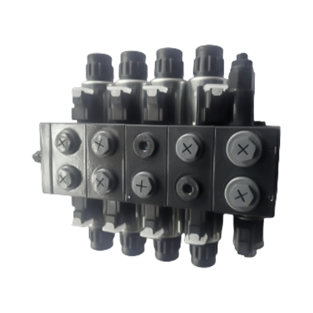
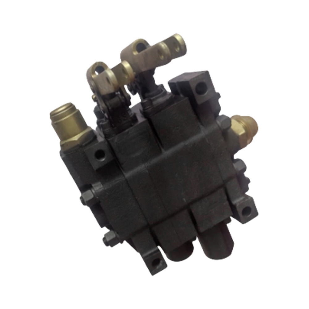
A Solenoid Directional Valve is the fundamental building block of modern hydraulic and pneumatic control systems. For design engineers and procurement specialists in automotive and agricultural machinery, understanding the working principles, electrical integration, and selection criteria for these valves is essential. This guide provides a detailed, engineer-level analysis of valve types, configurations, troubleshooting methods, and application-specific considerations.
A Solenoid Directional Valve directs the path of hydraulic fluid within a system. It uses an electromechanical solenoid to shift a spool, which opens or closes specific flow paths. This action controls the start, stop, and direction of hydraulic actuators such as cylinders or motors. Without these valves, automated and remote control of heavy machinery would be impossible.
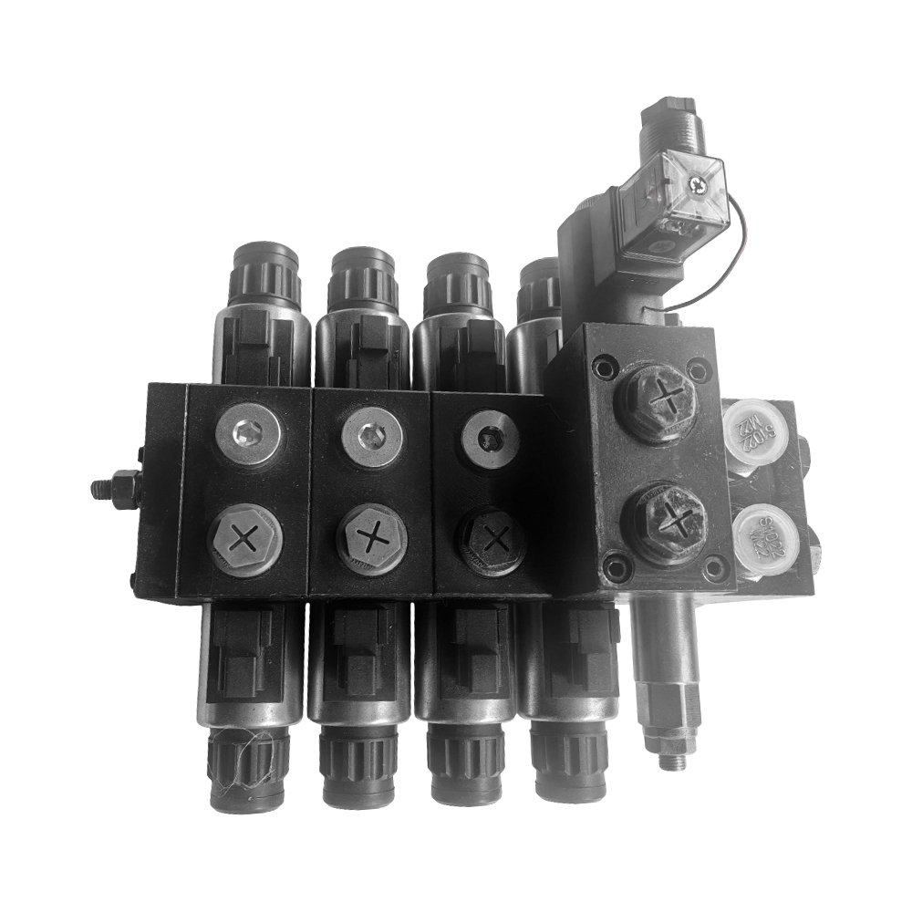
The valve consists of several precision-engineered components. The solenoid converts electrical energy into mechanical force to shift the spool within the precision-machined valve body. Return springs often reset the spool when the solenoid is de-energized. Valves are designated by the number of ports and positions, such as 2/2, 3/2, 4/2, 4/3, and 5/3 types.
The designation 5/3 indicates a valve with five ports and three distinct spool positions. The five ports typically consist of a pressure inlet (P), two cylinder ports (A and B), and two exhaust ports (R and S). The three positions allow for cylinder extension, retraction, and a center position where the spool can be configured for different functions. Understanding the 5/3 solenoid directional valve working principle is critical for applications requiring mid-stroke stopping of actuators.
The center position of a 5/3 valve defines the system's behavior when both solenoids are de-energized. Each configuration serves a specific engineering purpose.
In a typical 5/3 valve, energizing the left solenoid shifts the spool to the right, connecting P to A and B to S, extending a cylinder. Energizing the right solenoid shifts the spool left, connecting P to B and A to R, retracting the cylinder. When both solenoids are off, the spool returns to the center position, and the specific center configuration (open, closed, or tandem) determines the hydraulic state.
The choice between solenoid and manual actuation depends on the level of automation required and the operational environment. Each type offers distinct advantages.
Solenoid valves use electrical signals for remote or automated control, while manual valves require physical operator interaction. This fundamental difference dictates their application in modern machinery.
| Parameter | Solenoid Directional Valve | Manual Directional Valve |
|---|---|---|
| Actuation Method | Electromagnetic coil | Lever, handle, or foot pedal |
| Control Integration | Can be integrated with PLCs, sensors, and timers | Direct operator control only |
| Response Time | Fast (milliseconds) | Operator-dependent (slow) |
| Typical Applications | Automated production lines, mobile machinery with joystick control | Test stands, manual override circuits, simple machinery |
| Power Requirement | Requires electrical supply | No power required |
When evaluating solenoid directional valve vs manual directional valve, engineers must consider the need for automation, response time, and the availability of electrical power at the actuation point.
Correct electrical specification is critical for reliable operation. Solenoid coils are rated for voltage (24V DC is common in mobile equipment), current draw (inrush and holding), and duty cycle (continuous or intermittent). Using an incorrect coil rating leads to premature failure or failure to actuate.
The wiring method depends on whether the valve uses a single solenoid with spring return or dual solenoids. A 24v DC solenoid directional valve wiring diagram must be followed precisely to avoid short circuits and ensure proper function.
A typical 24v DC solenoid directional valve wiring diagram shows the connection points for the power supply, often including provisions for surge suppression diodes (also called flyback diodes) across the coil terminals. These diodes protect control circuits from voltage spikes generated when the coil is de-energized. Engineers must ensure that the wiring gauge matches the current draw and that all connections are properly insulated and protected from the environment.
Industries such as oil and gas, chemical processing, and mining often operate in environments where flammable gases, vapors, or dusts are present. These areas are classified according to standards like ATEX (Europe), IECEx (International), and NEC Class/Division (North America). Standard solenoid valves can ignite these atmospheres through electrical arcing or hot surfaces. Therefore, an explosion proof solenoid valve for hazardous areas is mandatory.
Explosion-proof valves are engineered to contain any internal ignition and prevent it from propagating to the external atmosphere.
When selecting an explosion proof solenoid valve for hazardous areas, engineers must verify that the valve's certification (e.g., ATEX II 2G Ex d IIC T6) matches the specific zone, gas group, and temperature class of the installation. Using uncertified components in these areas creates severe safety risks and legal liabilities.
Even the highest quality valves can encounter issues. Systematic hydraulic solenoid valve troubleshooting minimizes downtime and prevents unnecessary component replacement.
Failures typically fall into three categories: electrical, hydraulic, and mechanical. Identifying the correct category is the first step in troubleshooting.
A methodical approach isolates the root cause. Engineers should follow a step-by-step process.
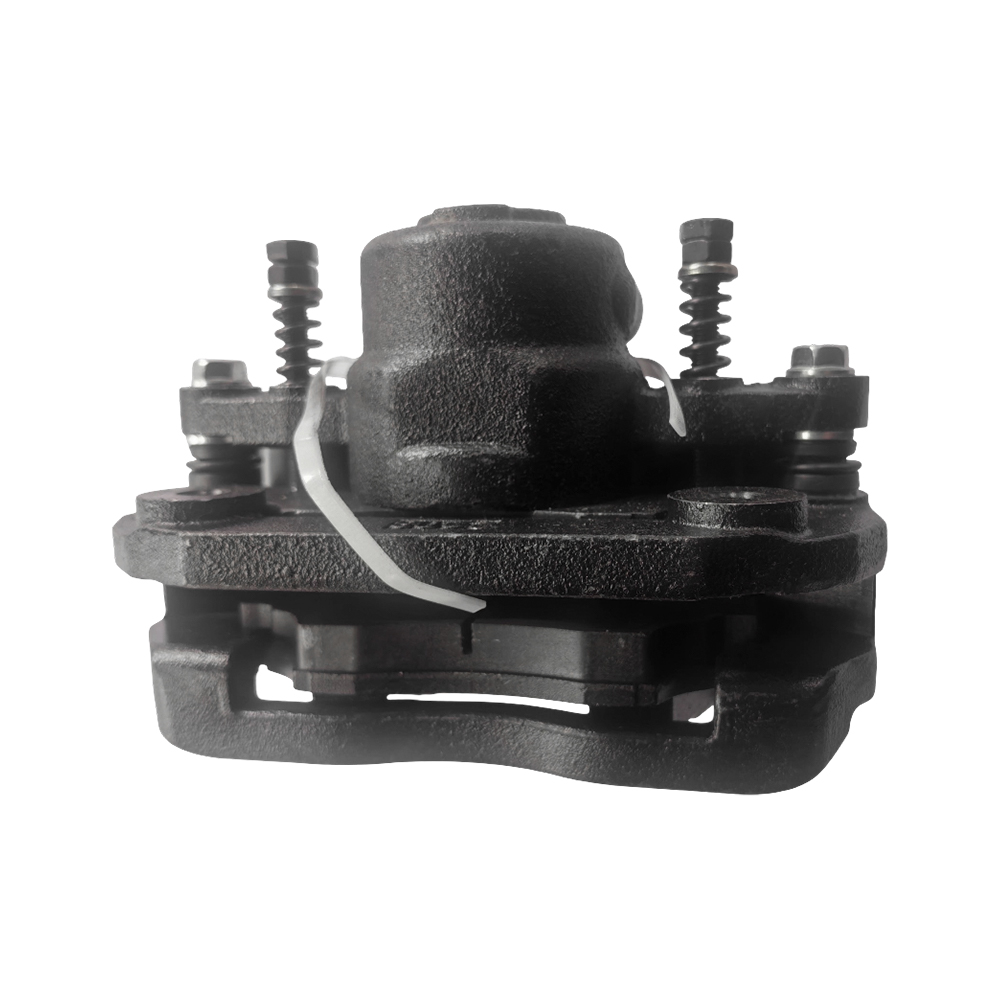
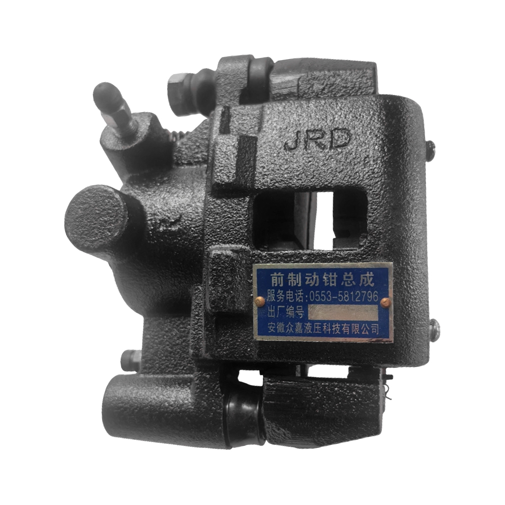
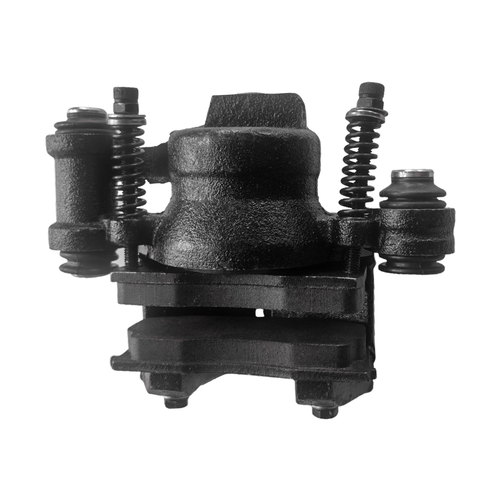
Hydraulic systems in automotive and agricultural machinery face unique challenges, including vibration, temperature extremes, and contamination. A manufacturer with deep application knowledge ensures that valves are designed for these conditions. For example, braking systems require failsafe operation, while agricultural implements need resistance to dust and moisture.
Anhui Zhongjia Hydraulic Technology Co., Ltd. is professional hydraulic directional control valves manufacturers and company in China, founded in 2020, the company is an enterprise integrating product design, research and development, production and sales of hydraulic systems and braking systems for automobiles and agricultural machinery. Based on the complete takeover of an enterprise that has been engaged in the industry for nearly 20 years, it has ensured the continuity of research and development, production, sales and service. This heritage means that when you specify a Solenoid Directional Valve from Anhui Zhongjia, you benefit from decades of accumulated engineering knowledge and proven field reliability.
The selection of a Solenoid Directional Valve requires a multi-faceted engineering evaluation. Engineers must understand the 5/3 solenoid directional valve working principle for applications needing mid-position control. They must weigh the pros and cons of solenoid directional valve vs manual directional valve based on automation needs. Proper electrical integration demands adherence to a 24v DC solenoid directional valve wiring diagram. For hazardous environments, an explosion proof solenoid valve for hazardous areas is non-negotiable. And when issues arise, systematic hydraulic solenoid valve troubleshooting ensures rapid resolution.
For your next hydraulic control project, partner with a manufacturer that combines recent founding energy with two decades of inherited expertise. Contact Anhui Zhongjia Hydraulic Technology Co., Ltd. to discuss your specific requirements for automotive or agricultural hydraulic systems.
A 4/3 valve has four ports (P, A, B, T) and three positions. A 5/3 valve has five ports (P, A, B, R, S) and three positions. The 5/3 valve provides separate exhaust ports for each cylinder port, allowing for independent control of exhaust backpressure and often enabling mid-position regenerative circuits.
No, you cannot. A 24V DC coil requires 24V DC to generate sufficient magnetic force to shift the spool. Applying 12V will result in weak or no actuation, and the coil may overheat if left energized due to higher than designed current draw relative to the holding force.
Choose a spring-centered valve (the spool returns to center when power is removed) for applications requiring a failsafe center position, such as stopping a cylinder when power is lost. Choose a detented valve (the spool remains in its last shifted position when power is removed) for applications where the actuator must hold its position even without electrical signal, such as a control valve on a mobile machine.
The "T" rating (Temperature Class) indicates the maximum surface temperature the valve can reach under operating conditions. For example, T6 means the maximum surface temperature is 85°C. This rating must be lower than the ignition temperature of the surrounding hazardous atmosphere to prevent fire or explosion.
Cold weather increases the viscosity of hydraulic oil. This thicker oil can create higher flow forces that the solenoid may struggle to overcome, especially if the valve is at the edge of its pressure specification. Additionally, moisture in the system can freeze, physically blocking spool movement. Using the correct viscosity grade for the ambient temperature is essential.
Recommended Products

Contact Info.
+86-159 9623 5291
No. 5, Chuangye Road, Niandou Industrial Park, Ma'anshan City, Anhui Province, China
MOBILE QR CODE
 English
  Español