en
Need Help Now? Call Us!
+86-159 9623 5291

Our team proudly offers an on-time guarantee and a 100% customer satisfaction guarantee.
Contact Online


 Home / News / Industry News / Agricultural Machinery Braking System: A Complete Engineering Guide for Buyers and Operators
  2026.03.24
  Industry News
 Content
A reliable agricultural machinery braking system is not optional equipment. It is a core safety and performance component that directly affects operator safety, field efficiency, and long-term maintenance costs. Whether you are a fleet manager, equipment wholesaler, or procurement engineer, understanding how these systems work at a technical level helps you make better sourcing decisions and reduces costly downtime.
This guide covers braking system types, hydraulic circuit design, failure prevention, performance optimization, and maintenance best practices. All five key topics are addressed with engineering-level depth.
Agricultural machinery operates in demanding environments. Uneven terrain, heavy loads, wet soil, and high-torque drivetrain forces all place extreme stress on braking components. A well-engineered agricultural machinery braking system must handle these variables consistently and predictably.
Agricultural braking systems must comply with international safety standards. Key standards include ISO 11684 for safety signs, ISO 4254-1 for general agricultural machinery safety, and OECD Code 6 for brake performance testing on tractors. Compliance with these standards is a baseline requirement for export-grade equipment and B2B procurement contracts.
Several braking technologies are used across the agricultural equipment sector. Each type has distinct engineering characteristics that make it suitable for specific machine categories and operating conditions.
Mechanical drum brakes use friction shoes that press outward against a rotating drum. They are simple, low-cost, and easy to service in the field. However, they generate significant heat under repeated heavy braking and require frequent adjustment as linings wear. They remain common on smaller tractors and utility vehicles where hydraulic systems are not cost-justified.
The hydraulic braking system for farm tractors using disc technology delivers superior stopping power and heat dissipation compared to drum designs. Wet disc brakes, which operate in an oil bath, are especially prevalent on high-horsepower tractors. The oil bath reduces wear, protects friction surfaces from contamination, and provides consistent pedal feel across varying temperatures.
Oil-immersed wet disc brakes are the dominant technology on tractors above 80 horsepower. The discs are submerged in transmission oil, which carries heat away from friction surfaces and prevents external contamination. These systems require minimal adjustment over their service life and are well suited to machines that operate in muddy or dusty environments.
Air-over-hydraulic systems combine a pneumatic circuit with a hydraulic actuator. Compressed air from a reservoir applies force to a hydraulic master cylinder, which then activates the wheel brakes. This design is common on large self-propelled sprayers and combine harvesters where pedal effort must be minimized and braking force must be consistent across all four corners.
The following table summarizes the key engineering differences between the four main system types. Each system offers a different balance of cost, performance, and maintenance requirements.
| System Type | Actuation | Heat Dissipation | Maintenance Interval | Typical Application | Relative Cost |
|---|---|---|---|---|---|
| Mechanical Drum | Cable / Rod | Low | Every 200–300 hours | Small tractors, utility vehicles | Low |
| Hydraulic Disc (Dry) | Hydraulic fluid | Medium | Every 500 hours | Mid-range tractors | Medium |
| Oil-Immersed Wet Disc | Hydraulic fluid | High | Every 1,000–1,500 hours | High-horsepower tractors | High |
| Air-Over-Hydraulic | Pneumatic + Hydraulic | High | Every 800–1,000 hours | Sprayers, combine harvesters | High |
The hydraulic braking system for farm tractors is the most widely used system architecture in modern agricultural machinery above 50 horsepower. Understanding its circuit topology and component functions is essential for procurement engineers and after-market parts suppliers.
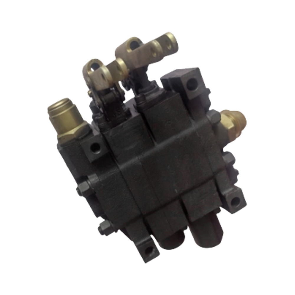
The master cylinder converts mechanical pedal force into hydraulic pressure. On tractors with independent left and right brake pedals, two separate master cylinders allow differential braking. This enables the operator to tighten turning radius by braking one rear wheel while the other continues to drive. Master cylinder bore diameter typically ranges from 19 mm to 25 mm depending on the required system pressure and pedal ratio.
Brake hydraulic lines must withstand peak pressures generated during hard braking events. Standard brake line operating pressure in agricultural tractors ranges from 60 bar to 120 bar. High-pressure reinforced hose assemblies conforming to SAE J1401 or ISO 3996 are required for all flexible sections. Rigid steel lines are preferred for fixed routing to minimize expansion under pressure and maintain pedal firmness.
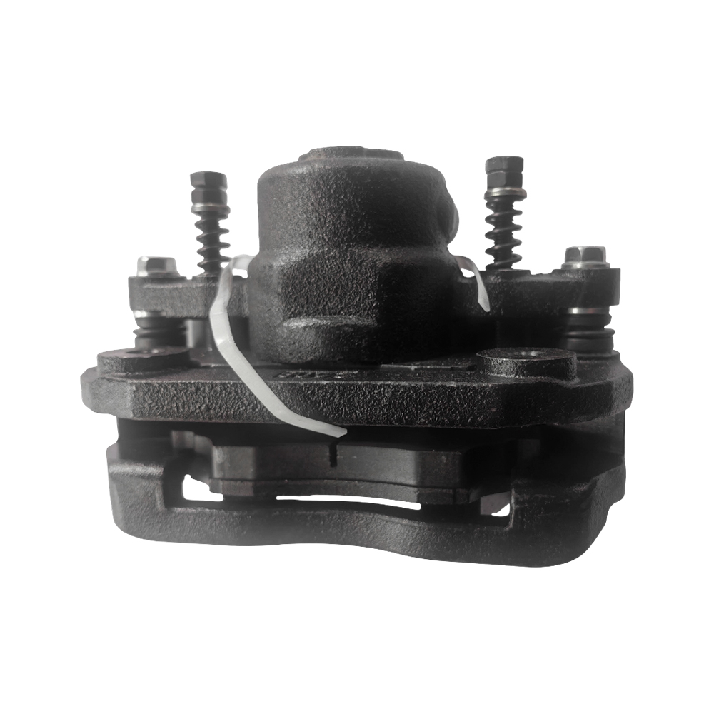
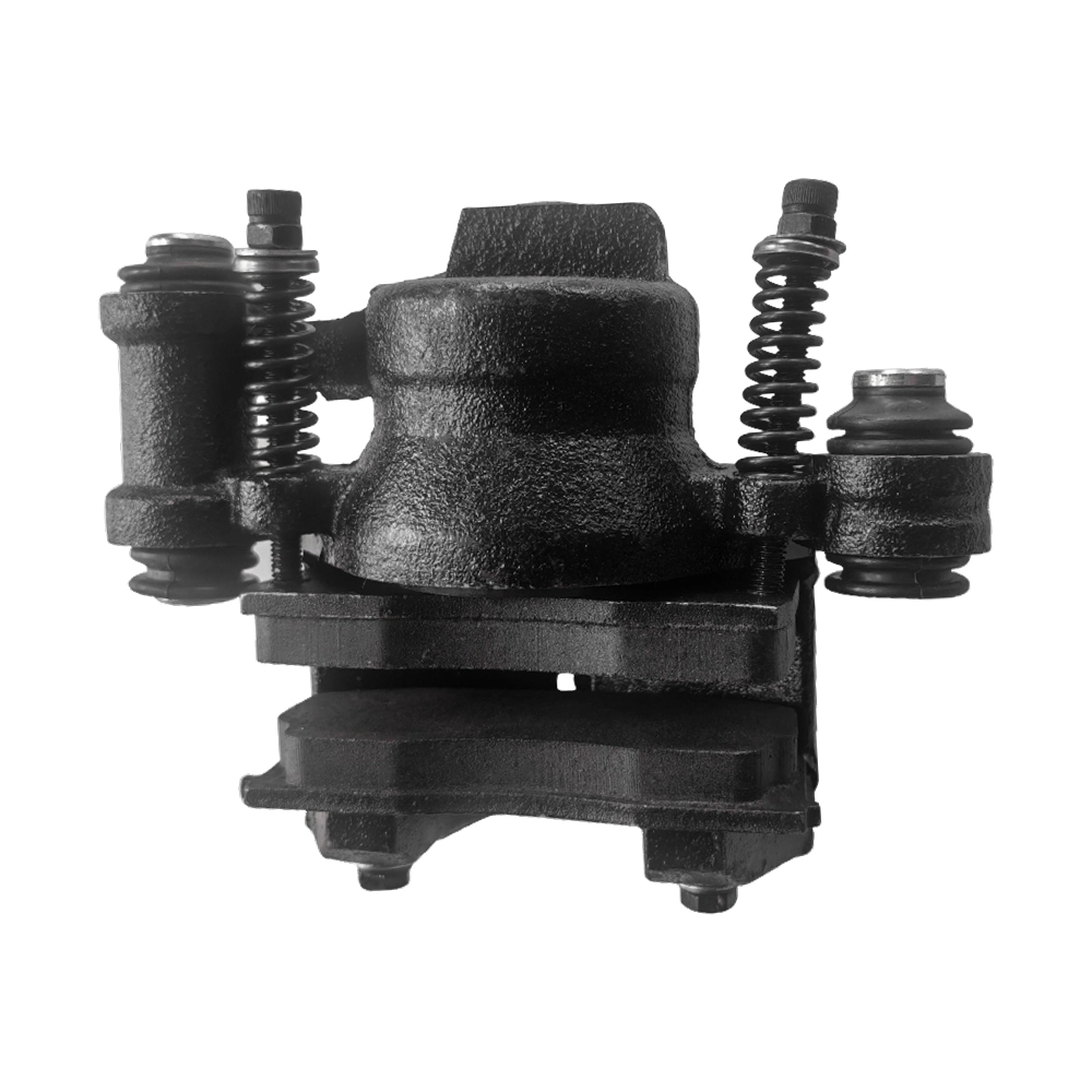
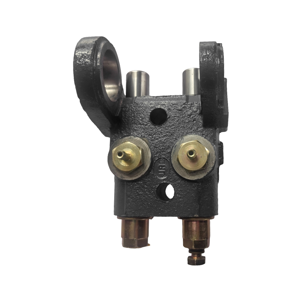
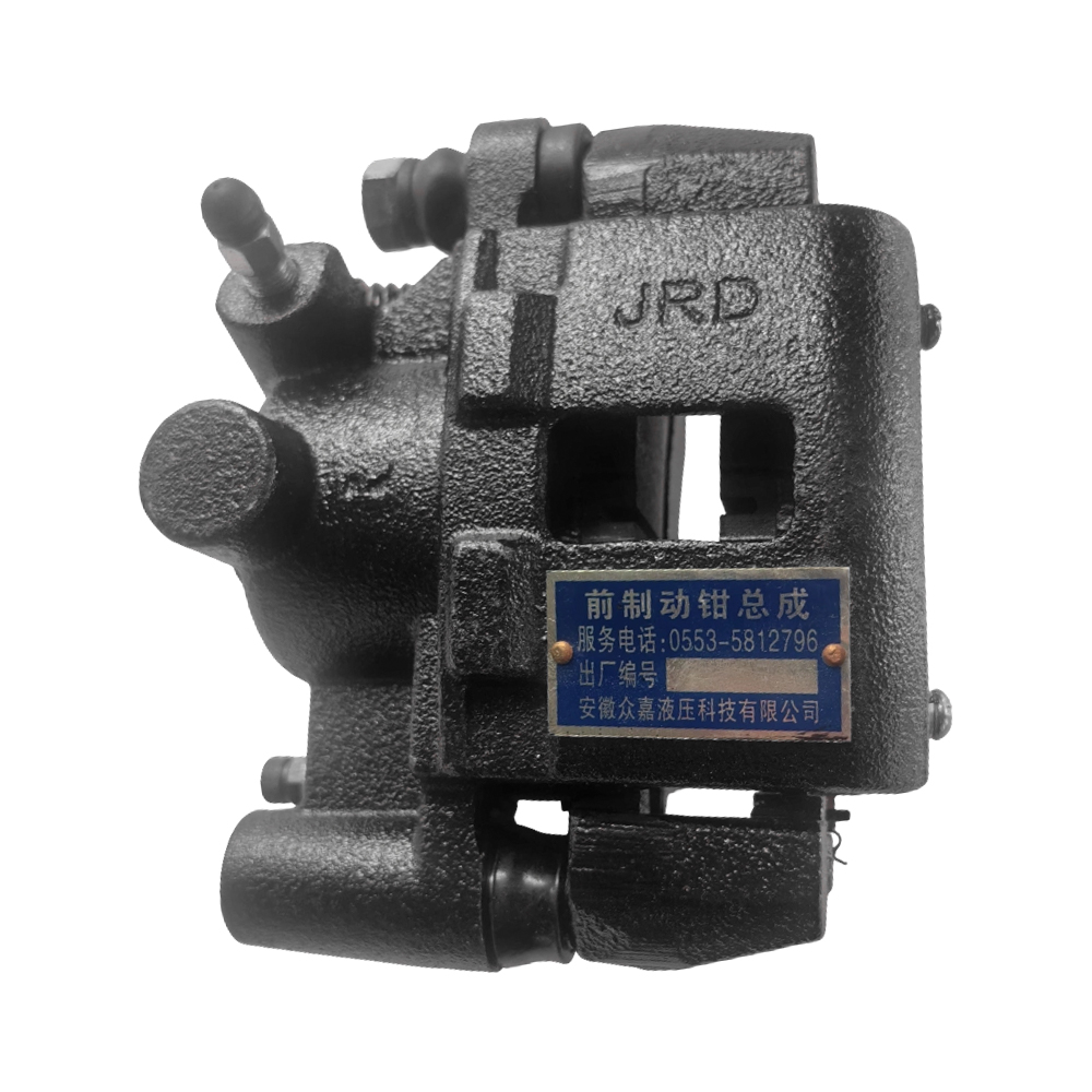
Hydraulic pressure from the master cylinder acts on a piston within the caliper or actuator housing. The piston forces friction material against the disc or drum surface. In wet disc systems, multiple thin steel discs are interleaved with friction-lined separator plates. The number of disc pairs determines total friction area and maximum torque absorption capacity. A typical 100-horsepower tractor brake assembly may use four to six disc pairs per side.
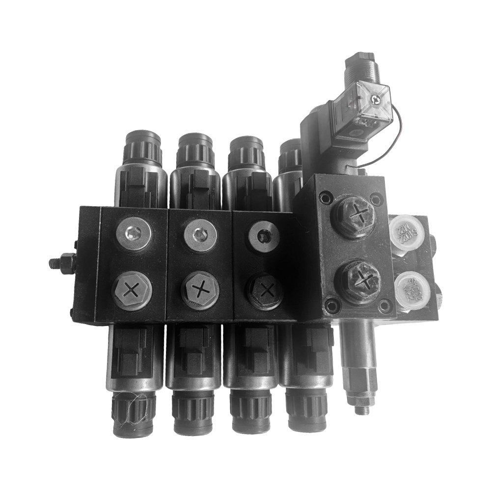
Modern tractor hydraulic brake circuits include provisions for trailer brake control. A trailer brake valve, connected to the tractor's brake pedal circuit, sends a proportional pressure signal to the trailer brake actuators. This ensures that the trailer decelerates in synchrony with the tractor, preventing jackknifing on slopes or during emergency stops. ISO 5692-2 defines the hydraulic connection standards for tractor-trailer brake circuits.
Understanding how to improve tractor brake performance is a priority for fleet managers who operate machines in demanding conditions. Performance improvements can be achieved through component upgrades, system calibration, and operational adjustments.
Friction material composition directly determines braking torque, heat tolerance, and wear rate. Sintered metallic linings offer higher coefficient of friction and better thermal stability than organic resin-bonded materials. For high-load applications such as hillside harvesting or heavy transport work, sintered materials are the preferred choice despite their higher unit cost.
Incorrect pedal free play is one of the most common causes of degraded braking performance. Insufficient free play causes the brakes to drag, generating heat and accelerating lining wear. Excessive free play reduces effective braking stroke and delays engagement. The standard free play specification for most tractor brake pedals is between 20 mm and 35 mm at the pedal pad. This specification must be verified during each scheduled service interval.
Brake fluid moisture absorption is a critical performance factor. Brake fluid that has absorbed more than 3.5% water by volume experiences a significant reduction in boiling point, which can cause vapor lock during extended braking on long downhill grades. Fluid should be tested annually using a refractometer or brake fluid test strips and replaced whenever moisture content exceeds the manufacturer's specification.
Scoring, grooves, and thermal cracking on disc or drum surfaces reduce effective contact area and increase stopping distance. Discs with surface runout exceeding 0.15 mm or thickness variation greater than 0.025 mm should be resurfaced or replaced. Regular visual inspection during oil changes provides an opportunity to detect surface degradation before it becomes a safety issue.
The following table compares typical brake performance metrics before and after applying the improvement measures described above.
| Performance Metric | Before Improvement | After Improvement |
|---|---|---|
| Stopping distance at 25 km/h (full load) | 12–15 m | 8–10 m |
| Brake fluid boiling point | 155°C (contaminated) | 205°C (fresh fluid) |
| Pedal travel to full engagement | 65–80 mm | 45–55 mm |
| Disc surface runout | 0.20–0.30 mm | <0.10 mm |
| Lining wear rate (per 100 operating hours) | 0.8–1.2 mm | 0.3–0.5 mm |
Effective agricultural equipment brake failure prevention requires a systematic approach that combines scheduled maintenance, operator training, and real-time condition monitoring. Brake failures in agricultural settings carry serious consequences, including machine rollovers on slopes and uncontrolled collisions with implement attachments.
A structured maintenance schedule is the most effective tool for agricultural equipment brake failure prevention. The following table outlines recommended inspection and service intervals based on machine operating hours.
| Service Item | Interval (Operating Hours) | Action Required |
|---|---|---|
| Pedal free play check | Every 50 hours | Inspect and adjust to specification |
| Brake fluid moisture test | Every 500 hours or annually | Test and replace if moisture >3.5% |
| Lining thickness measurement | Every 250 hours | Replace if below minimum thickness |
| Hydraulic line inspection | Every 500 hours | Check for cracks, abrasion, and leaks |
| Disc surface runout measurement | Every 1,000 hours | Resurface or replace if out of tolerance |
| Parking brake functional test | Every 250 hours | Verify hold capacity on 20% grade |
| Wet disc oil bath change | Every 1,000–1,500 hours | Drain, flush, and refill with specified oil |
Operator behavior is a significant variable in brake failure prevention. Operators should perform a pre-operation brake check before each shift. This check includes verifying pedal resistance, testing parking brake engagement, and confirming that both independent pedals respond symmetrically. Operators working on slopes steeper than 15 degrees should receive specific training on avoiding brake fade through gear selection and engine braking techniques.
Selecting the best braking system for heavy farm machinery requires matching system architecture to machine weight class, operating environment, and duty cycle. There is no single universal answer, but engineering analysis consistently points to oil-immersed wet disc brakes as the most appropriate technology for machines above 120 horsepower operating in mixed-terrain environments.
The following table provides a procurement-level overview of recommended braking system types by machine category and weight class.
| Machine Category | Operating Weight | Recommended System | Key Selection Reason |
|---|---|---|---|
| Compact utility tractor | 800–2,500 kg | Mechanical drum or dry disc | Low cost, simple field repair |
| Mid-range row crop tractor | 2,500–6,000 kg | Hydraulic wet disc | Differential steering, moderate loads |
| High-horsepower tractor | 6,000–15,000 kg | Oil-immersed wet disc | High torque, continuous duty, low maintenance |
| Self-propelled sprayer | 5,000–12,000 kg (loaded) | Air-over-hydraulic disc | Low pedal effort, all-corner balance |
| Combine harvester | 10,000–25,000 kg | Air-over-hydraulic disc | High deceleration demand, large mass |
Heavier machines require braking systems with greater thermal capacity and higher friction torque ratings. The challenge is that increasing friction area and disc count raises system weight and cost. Engineers use specific energy absorption calculations to verify that a chosen system can absorb all kinetic energy during a maximum-load emergency stop without exceeding the thermal limit of the friction material. This calculation is expressed as:
Specific energy absorption (J/mm²) = (0.5 × M × V²) / total friction area
Where M is vehicle mass in kilograms and V is initial velocity in meters per second. Friction materials for heavy agricultural machinery are typically rated between 0.5 J/mm² and 1.2 J/mm² for a single stop event.
Practical agricultural machinery braking system maintenance tips extend component service life, reduce unplanned downtime, and lower total ownership cost. The following recommendations are drawn from field service data and engineering best practices.
Water and dirt contamination in the oil bath of a wet disc system accelerates friction disc wear and causes corrosion on steel separator plates. Technicians should inspect axle seals and transmission case gaskets at each oil change interval. Oil samples taken from the wet disc sump should be analyzed for water content, metal particle concentration, and viscosity. An increase in metal particle count above 150 ppm indicates abnormal wear and requires further inspection before the next scheduled service.
Air trapped in a hydraulic brake circuit causes a spongy pedal feel and reduces braking effectiveness. Correct bleeding requires starting at the caliper or actuator farthest from the master cylinder and working progressively toward the master cylinder. A pressure bleeder set to 1.0–1.5 bar provides more consistent results than manual pedal-pumping methods. The circuit is fully bled when fluid exits the bleed valve in a clear, bubble-free stream.
Parking brake cables stretch over time and accumulate corrosion at pivot points. Cable inner wire diameter loss of more than 10% indicates fatigue and requires replacement. Pivot pins and clevis connections should be cleaned and lubricated with grease rated for high-load, slow-movement applications such as NLGI Grade 2 lithium-complex grease. Lubrication at these points should be performed every 250 operating hours.
Machines stored for extended periods are vulnerable to disc and drum corrosion, which causes initial brake judder when the machine returns to service. Before storage, operators should apply the parking brake firmly for a short period, then release it. This seats the friction surfaces evenly and prevents the pads from bonding to the disc surface. For storage periods exceeding three months, applying a thin film of corrosion-inhibiting oil to exposed drum or disc surfaces is recommended.
Oil-immersed wet disc brakes are the most reliable option for hillside operations. They offer superior heat dissipation, consistent friction performance regardless of soil contamination, and a longer service interval than dry disc or drum alternatives. For machines operating continuously on grades above 15 degrees, the wet disc system's ability to shed heat through the transmission oil circuit prevents the brake fade that is common with dry systems under similar conditions.
Brake fluid should be tested at least once per year or every 500 operating hours, whichever comes first. Replacement is necessary when moisture content exceeds 3.5% by volume or when the fluid shows visible contamination. In regions with high humidity or machines that experience frequent water crossings, testing frequency should be increased to every 250 hours. Using fluid that meets or exceeds ISO 4925 Class 4 specification provides an adequate safety margin for most agricultural operating temperatures.
Uneven braking is most commonly caused by unequal lining wear between the two sides, a seized caliper piston on one side, or a difference in hydraulic pressure reaching each brake actuator. Contaminated fluid causing a sticky master cylinder on one pedal circuit is another frequent cause. Technicians should begin diagnosis by measuring pedal travel and comparing hydraulic pressure output on both sides using a calibrated pressure gauge. Lining thickness measurements on both sides should be compared as part of the same inspection.
This conversion is generally not recommended and is rarely cost-effective in practice. Wet disc systems are designed with lower friction coefficients per disc pair, which is compensated by using multiple disc pairs and the thermal management provided by the oil bath. A dry disc replacement system would require significantly larger disc diameters or additional friction surface area to achieve equivalent braking torque. The cost of redesigning caliper housings, modifying axle housings, and procuring custom components typically exceeds the maintenance savings over any reasonable service life projection.
Procurement engineers should verify the following specifications: friction material coefficient of friction rating (static and dynamic), maximum operating temperature rating of the friction material, disc or drum material grade and hardness specification, hydraulic component pressure ratings and seal material compatibility with the specified brake fluid, and dimensional tolerances for all mating surfaces. OEM part number cross-references should be validated against the original equipment manufacturer's service manual, and material certifications should be requested for all friction components used in safety-critical applications.
Recommended Products

Contact Info.
+86-159 9623 5291
No. 5, Chuangye Road, Niandou Industrial Park, Ma'anshan City, Anhui Province, China
MOBILE QR CODE
 English
  Español