en
Need Help Now? Call Us!
+86-159 9623 5291

Our team proudly offers an on-time guarantee and a 100% customer satisfaction guarantee.
Contact Online


 2026.03.06
  Industry News
 Content
Directional control valves manage fluid flow paths in hydraulic and pneumatic systems, determining actuator direction and position. This guide examines port configurations, actuation methods, and performance characteristics for industrial machinery and mobile equipment applications.
Directional control valves contain sliding spools or poppet elements that connect or isolate fluid ports based on position. The valve directs pressurized fluid to one side of an actuator while exhausting fluid from the opposite side, creating controlled motion.
Key functional parameters include:
Anhui Zhongjia Hydraulic Technology Co., Ltd. operates as a professional hydraulic directional control valve manufacturer in China, founded in 2020. The company integrates product design, research and development, production, and sales of hydraulic systems and braking systems for automobiles and agricultural machinery. The organization assumed complete operations from an enterprise with nearly 20 years of industry experience, ensuring continuity in technical development, manufacturing capability, and customer service.
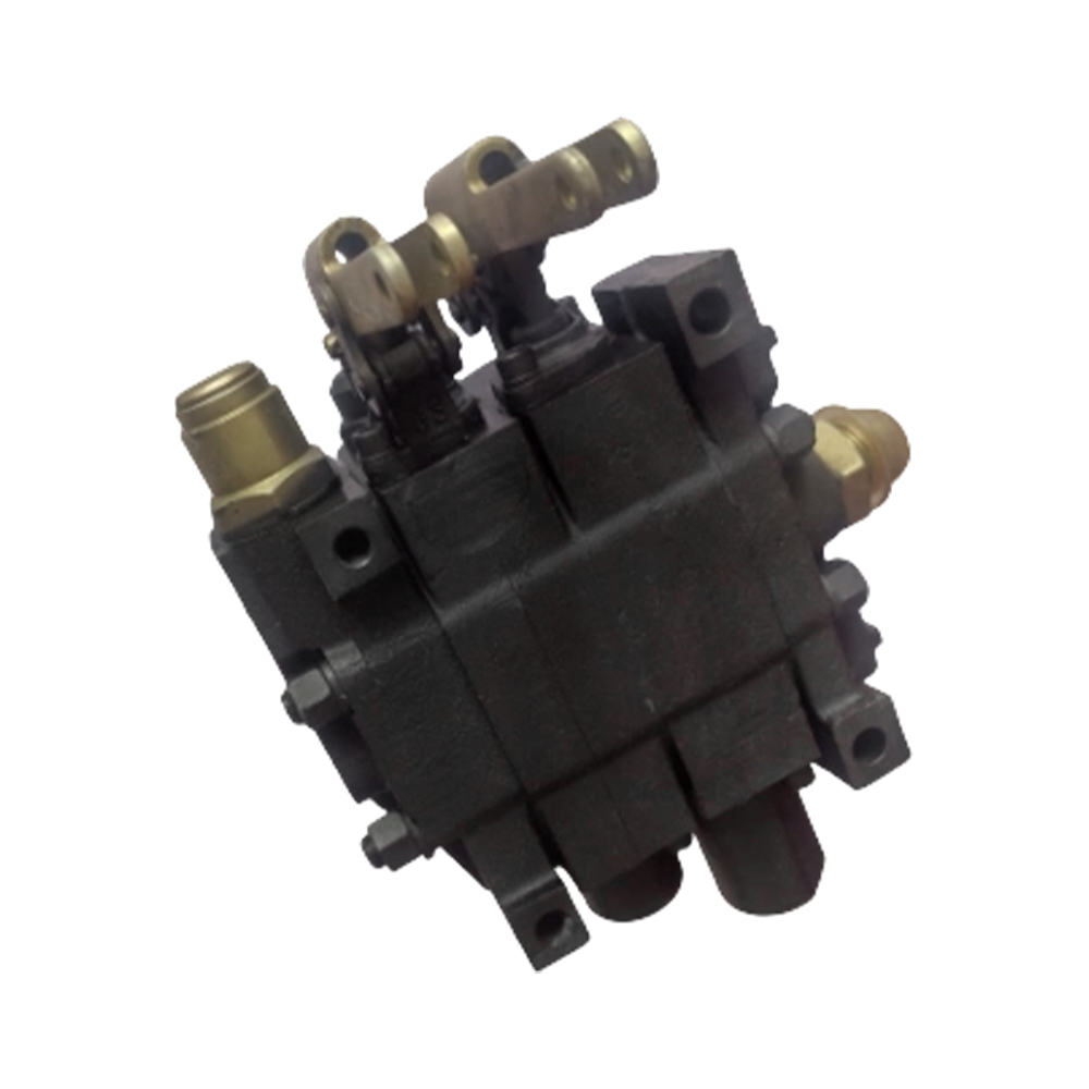
The 5/2 designation indicates five connection ports and two stable positions. Five ports include pressure supply, two cylinder connections, and two exhaust paths. This configuration controls double-acting pneumatic cylinders requiring pressurized extension and retraction.
Port function assignment:
Actuation method comparison:
| Characteristic | Single Solenoid (Spring Return) | Double Solenoid (Pulsed) |
| Power Consumption | Continuous during actuation only | Pulse only, no holding power |
| Fail-Safe Position | Defined by spring (home position) | Remains in last position (no default) |
| Electrical Safety | Safe on power loss | Requires separate safety logic |
| Switching Frequency | Limited by spring fatigue | Higher (no spring stress) |
| Typical Application | Intermittent cycling | Continuous high-speed operation |
The pneumatic directional control valve 5/2 way dominates factory automation due to clear functional logic and reliable cylinder control. Double-solenoid versions suit applications requiring position retention during electrical interruptions.
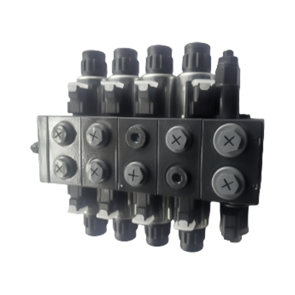
CETOP 3 (Comité Européen des Transmissions Oléohydrauliques et Pneumatiques) designates a standardized mounting interface corresponding to ISO 4401-03 and NFPA D03. The pattern enables vertical stacking of multiple valves on common manifolds.
Interface specifications include:
Mounting style comparison:
| Configuration | Inline (Pipe Connected) | CETOP 3 Modular |
| Installation Time | 2-4 hours (cutting, threading, sealing) | 30 minutes (stack and torque) |
| Leak Points | Multiple threaded connections | O-ring seals only |
| Maintenance Access | Disassemble piping | Remove individual valve |
| System Flexibility | Fixed configuration | Add or remove functions easily |
| Space Requirement | Extensive (pipe bending radius) | Compact (vertical stacking) |
A hydraulic directional control valve cetop 3 configuration suits mobile machinery and industrial presses requiring compact valve packages. The standardized interface allows sourcing from multiple suppliers without manifold redesign.
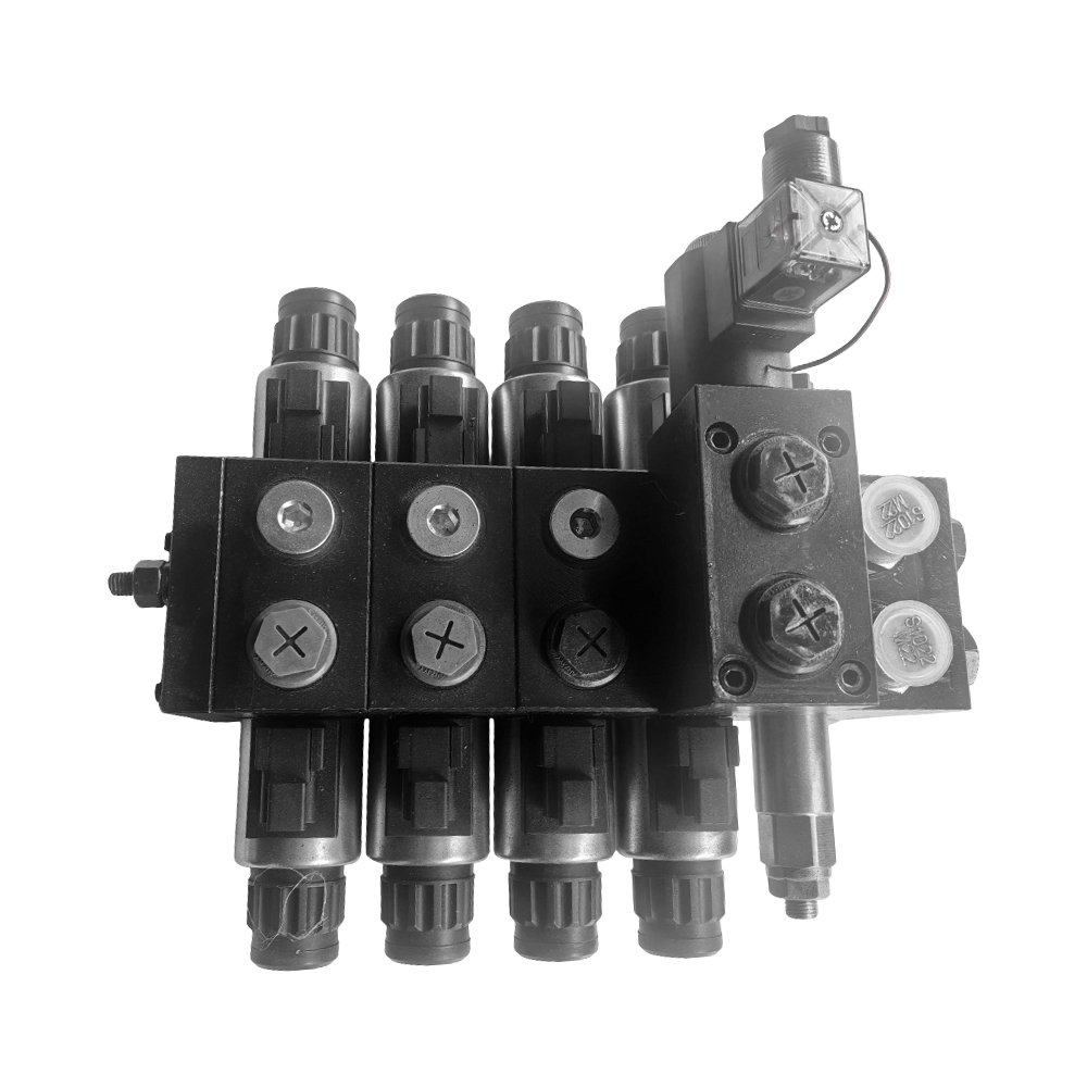
Solenoid actuation converts electrical signals into mechanical force displacing the valve spool. Twenty-four volt DC represents the industrial standard for safety and compatibility with programmable logic controllers.
Electrical characteristics include:
Coil technology comparison:
| Parameter | Standard DC Solenoid | High-Performance DC Solenoid |
| Pull-In Force | 30-40 Newtons | 60-80 Newtons |
| Response Time | 50-100 milliseconds | 20-40 milliseconds |
| Power Consumption | 30-50 watts continuous | 50-80 watts (reduced holding) |
| Operating Temperature | -20 to +70°C | -40 to +80°C |
| Price Premium | Baseline | 40-60% increase |
The solenoid directional control valve 24v dc specification dominates mobile hydraulic applications due to battery compatibility and safety voltage limits. High-performance coils justify investment for high-frequency switching or cold climate operations.
Lever-operated valves provide direct mechanical control independent of electrical systems. The operator physically shifts the spool through linkages or direct connection, ensuring functionality during power failures or maintenance.
Ergonomic design considerations include:
Actuation method comparison:
| Scenario | Solenoid Actuation | Lever Operation |
| Power Failure Response | System shutdown or default position | Unaffected, continuous control |
| Operator Skill Requirement | Electrical troubleshooting | Mechanical system knowledge |
| Response Speed | Fast (electronic signal) | Slow (human reaction time) |
| Precision Positioning | Accurate (proportional available) | Approximate (on-off typical) |
| Maintenance Complexity | Coil replacement, wiring | Linkage lubrication, seal wear |
Manual directional control valve lever operated configurations serve as emergency backups in critical systems and primary controls in simple machinery. The direct mechanical connection eliminates electrical fault modes, providing reliability in harsh electromagnetic environments.
Proportional valves modulate flow rate through spool position control rather than simple on-off shifting. Closed center configurations block all ports in the neutral position, maintaining system pressure and actuator position.
Center configuration comparison:
| Type | Open Center (P Connected to T) | Closed Center (All Ports Blocked) |
| Pump Unloading | Yes (low pressure standby) | No (relief valve required) |
| Energy Consumption | Low at idle | High (continuous pressure) |
| Actuator Drift | Possible (leakage paths) | Minimal (locked position) |
| System Response | Delayed (pressure build required) | Immediate (pressure maintained) |
| Typical Application | Fixed-displacement pump systems | Variable-displacement, precision holding |
The proportional directional control valve closed center suits servo-controlled positioning systems requiring precise velocity profiles and position holding. The blocked-center design eliminates cross-port leakage causing cylinder drift in open-center alternatives.
Valve sizing requires balancing flow capacity against energy losses:
Spool-valve clearance creates inevitable leakage from high-pressure to low-pressure ports:
Mobile equipment imposes specific constraints on valve selection:
Anhui Zhongjia Hydraulic Technology applies nearly 20 years of accumulated industry experience to address these specialized requirements through integrated system design.
Proper valve mounting requires precision machining:
Valve reliability depends on contamination control:
5/2 valves provide independent exhaust paths for each cylinder port, enabling speed control through exhaust throttling and preventing cross-contamination between extend and retract circuits. 4/2 valves share a common exhaust, simplifying piping but limiting control flexibility. The pneumatic directional control valve 5/2 way dominates double-acting cylinder applications; 4/2 valves suit single-acting cylinders or hydraulic systems with dedicated return lines.
CETOP 3 valves handle maximum flows of 40 liters per minute, suitable for small cylinders and pilot circuits. CETOP 5 (ISO 4401-05, NFPA D05) accommodates 80-120 liters per minute for medium industrial actuators. The hydraulic directional control valve cetop 3 specification optimizes space and cost for flows below 30 liters per minute; larger flows require CETOP 5, 7, or 8 interfaces with correspondingly larger port diameters.
Standard industrial solenoid coils meet Class F (155°C maximum winding temperature) or Class H (180°C). The solenoid directional control valve 24v dc coils operate with 80-100°C temperature rise above ambient, requiring Class F minimum for 50°C ambient environments. Tropical or continuous-duty applications specify Class H for additional thermal margin.
OSHA 1910.147 (Lockout/Tagout) and ISO 14118 (Safety of Machinery) require positive mechanical isolation during maintenance. Manual directional control valve lever operated configurations for hazardous energy control must incorporate lockable detents or removable handles preventing accidental or unauthorized operation. Detent mechanisms withstand 200 Newtons force without position change.
Proportional valves require electronic amplifiers converting command signals (0-10V or 4-20mA) into current-controlled solenoid drive. The proportional directional control valve closed center specification needs amplifiers with dither frequency (typically 100-250 Hz) preventing spool sticking and deadband compensation improving resolution. Amplifier selection matches valve coil resistance (typically 20-30 ohms) and required response bandwidth.
Selecting appropriate directional control valves requires analysis of fluid medium, flow requirements, actuation method, and control precision. Whether specifying pneumatic directional control valve 5/2 way for cylinder control, hydraulic directional control valve cetop 3 for modular integration, solenoid directional control valve 24v dc for electrical automation, manual directional control valve lever operated for emergency backup, or proportional directional control valve closed center for precision positioning, technical specifications determine system performance.
Anhui Zhongjia Hydraulic Technology Co., Ltd. provides integrated hydraulic system design and manufacturing, leveraging nearly 20 years of industry continuity to support automotive and agricultural machinery applications.

Contact Info.
+86-159 9623 5291
No. 5, Chuangye Road, Niandou Industrial Park, Ma'anshan City, Anhui Province, China
MOBILE QR CODE
 English
  Español