en
Need Help Now? Call Us!
+86-159 9623 5291

Our team proudly offers an on-time guarantee and a 100% customer satisfaction guarantee.
Contact Online


 Home / News / Industry News / Technical Analysis of Wet-Pin Solenoid Design in Hydraulic Solenoid Directional Control Valve Systems
  2026.05.10
  Industry News
 Content
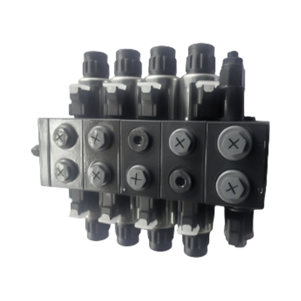
1. The wet-pin solenoid design in a Hydraulic Solenoid Directional Control Valve allows the armature to operate submerged in hydraulic fluid, which serves as a natural lubricant and thermal conductor.
2. When evaluating how wet-pin solenoids improve valve response time, engineers observe the elimination of dynamic oil seals that otherwise create mechanical friction and drag against the plunger's stroke.
3. For a high-performance Hydraulic Solenoid Directional Control Valve, the fluid surrounding the armature provides critical damping that minimizes "spool bounce" during high-frequency switching cycles.
4. The impact of armature stroke length on switching speed is significantly reduced in wet-pin configurations because the hydraulic fluid assists in heat dissipation, allowing for higher coil wattage and stronger initial magnetic pull.
1. Why spool-to-bore clearance affects internal leakage: A Hydraulic Solenoid Directional Control Valve relies on a precision-ground fit where the radial clearance is often held between 2 to 6 micrometers to maintain system pressure while ensuring fluid film lubrication.
2. Achieving a specific Ra surface finish (typically 0.4 micrometers) on the valve spool is vital to minimize internal leakage in hydraulic directional valves, ensuring that volumetric efficiency remains above 95 percent at maximum operating pressures of 315 bar.
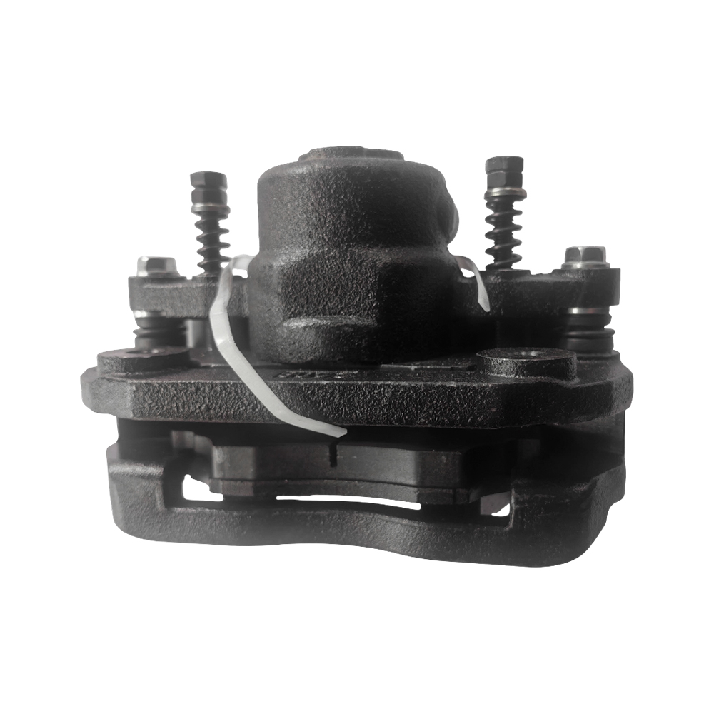
3. In a Hydraulic Solenoid Directional Control Valve, the use of hardened alloy steel with a tensile strength exceeding 600 MPa prevents the spool from deforming under transient pressure spikes.
4. Testing the hysteresis of hydraulic solenoid valves involves measuring the lag between the electrical signal input and the actual mechanical shift; wet-pin designs consistently show lower hysteresis compared to dry-pin variants due to reduced stick-slip friction.
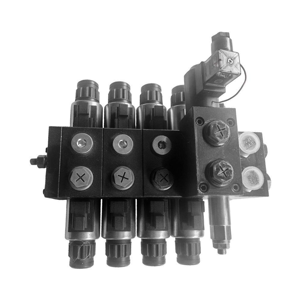
1. Analyzing the thermal dissipation of wet-pin solenoids: Since the hydraulic oil acts as a heat sink, the Hydraulic Solenoid Directional Control Valve can operate at 100 percent ED (duty cycle) without the coil temperature exceeding the Class H insulation limit of 180 degrees Celsius.
2. Comparing AC vs DC solenoids for directional control: While AC solenoids offer faster initial actuation, DC wet-pin solenoids are preferred for Hydraulic Solenoid Directional Control Valve applications requiring smoother transitions and longer mechanical life due to the absence of "inrush" current vibration.
3. Optimizing solenoid coil wattage for extreme temperatures involves selecting windings that maintain magnetic flux density even as electrical resistance increases with ambient heat.
4. Solenoid Configuration Performance Matrix:
| Engineering Metric | Dry-Pin Solenoid Design | Wet-Pin Hydraulic Solenoid Directional Control Valve |
| Seal Friction | High (Dynamic O-Rings) | Negligible (Static Sealing) |
| Heat Dissipation | Air-Cooled (Low Efficiency) | Oil-Cooled (High Efficiency) |
| Mechanical Life | ~5 Million Cycles | >10 to 20 Million Cycles |
| Ingress Protection | Typically IP65 | IP67 / IP69K Available |
1. Does an IP67 rated coil extend MTBF? In mobile machinery, protected coils prevent moisture ingress that causes short circuits, effectively doubling the Mean Time Between Failure for a Hydraulic Solenoid Directional Control Valve in outdoor environments.
2. How to reduce hydraulic shock with cushioned spool notches: By customizing the spool land geometry with V-notches, the Hydraulic Solenoid Directional Control Valve can gradually open flow passages, preventing the impact of pressure surges on valve durability.
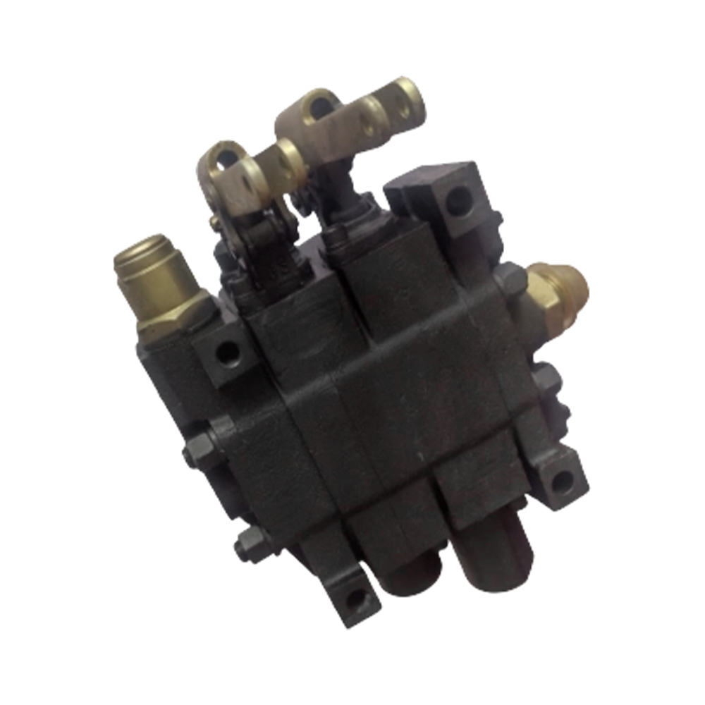
3. Implementing manual override features for solenoid valves allows for mechanical actuation during electrical failures, a critical safety standard for industrial Hydraulic Solenoid Directional Control Valve installations.
1. What is the primary advantage of a wet-pin solenoid?
The primary advantage in a Hydraulic Solenoid Directional Control Valve is the elimination of the dynamic seal on the armature pin, which drastically reduces friction, improves heat transfer, and protects the armature from external corrosion.
2. Can hydraulic fluid viscosity affect response time?
Yes. High-viscosity fluid at low temperatures can increase the drag on the armature. However, how wet-pin solenoids improve valve response time is most apparent once the system reaches an operating temperature where fluid resistance is minimized.
3. What is the standard mounting interface for these valves?
Most Hydraulic Solenoid Directional Control Valve units follow the ISO 4401 (CETOP) standard, such as size 03 (NG6) or size 05 (NG10), ensuring global interchangeability for subplate mounting.
4. Why do DC solenoids last longer than AC solenoids?
DC solenoids in a Hydraulic Solenoid Directional Control Valve do not suffer from the "hum" or vibration caused by the 50/60Hz cycle, and they do not have the high inrush current that can burn out AC coils if the spool becomes jammed.
5. What is "spool sticking" and how is it prevented?
Spool sticking occurs due to silting (particulate buildup) or thermal expansion. It is prevented by maintaining high fluid cleanliness (ISO 4406 18/16/13) and utilizing Hydraulic Solenoid Directional Control Valve bodies with high tensile strength to resist bore distortion.
1. ISO 4401: Hydraulic fluid power — Four-port directional control valves — Mounting surfaces.
2. NFPA/T2.6.1: Method for Verifying the Fatigue and Static Pressure Ratings of the Pressure Containing Envelope of a Metal Fluid Power Component.
3. IEC 60529: Degrees of protection provided by enclosures (IP Code) for electrical equipment.
Recommended Products

Contact Info.
+86-159 9623 5291
No. 5, Chuangye Road, Niandou Industrial Park, Ma'anshan City, Anhui Province, China
MOBILE QR CODE
 English
  Español