In hydraulic and pneumatic control systems, the Manual Directional Valve serves as the primary interface for human-to-machine control. It is a fundamental component that changes the flow path of pressurized media (oil or air) through the physical displacement of an internal spool, directly governing the start, stop, and direction of actuators such as cylinders or motors. Despite the rise of electronic automation, manual valves remain essential due to their tactile feedback, intrinsic safety, and unmatched reliability in harsh environments.
The Core Value of Manual Control
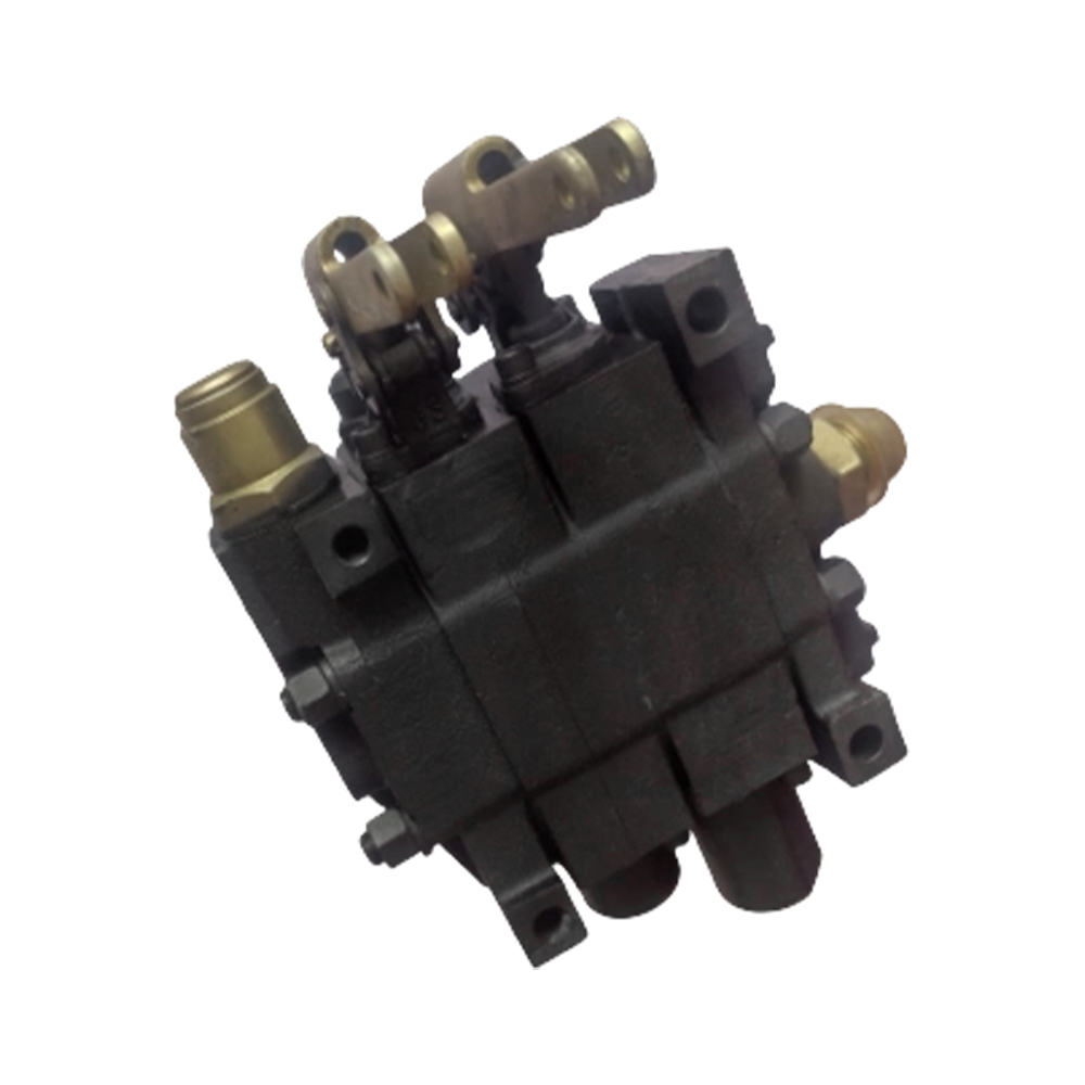
- Definition and Mechanical Logic: A manual directional valve consists of a valve body, a sliding spool, positioning elements (like springs or detents), and an operating lever. By manually pivoting the lever, the operator moves the spool axially within the bore, aligning internal galleries to connect or block specific ports.
- Functional Versatility: Beyond simply reversing motion, these valves facilitate complex system behaviors, such as pressure unloading or load holding, depending on the internal spool configuration (center condition).
- Strategic Advantages:
- Reliability: They operate independently of electrical power, making them ideal for emergency overrides or remote mobile equipment.
- Durability: Built with robust cast iron or steel bodies, they withstand high-pressure spikes and external mechanical stress better than sensitive solenoid-actuated counterparts.
- Precision Control: Operators can "throttle" the flow by partially shifting the lever, allowing for smoother acceleration and deceleration of heavy loads through manual feathering.
In-Depth Comparison of Technical Parameters
Selecting the correct manual directional valve requires a precise evaluation of system requirements. The following table highlights the critical differences in parameters across common application tiers:
| Parameter Dimension |
Light Industrial / Pneumatic |
Heavy Duty / Hydraulic Systems |
| Nominal Pressure |
Typically < 1.0 MPa (145 PSI) |
Up to 21 MPa - 35 MPa (3000-5000+ PSI) |
| Flow Capacity |
Low to medium flow for rapid cycling |
High flow (e.g., 60-150 L/min) to drive heavy actuators |
| Internal Leakage |
Must be near zero to prevent air loss |
Minimal allowable leakage based on spool clearance fits |
| Fluid Compatibility |
Compressed air (lubricated or dry) |
Mineral oils, water-glycols, or synthetic fluids |
When finalizing a specification, the Center Function (e.g., Closed Center, Open Center, or Tandem Center) is often the most vital decision. For instance, a Tandem Center (Type PT) allows the pump to unload to the tank at low pressure while keeping the cylinder ports blocked, which is a highly efficient choice for multi-valve mobile circuits.
Working Principles and Core Construction
The operational efficiency of a Manual Directional Valve relies on the precise mechanical interaction between the internal spool and the stationary valve body. Understanding these internal mechanics is essential for diagnosing system behavior and ensuring long-term operational stability.
1. The Spool-and-Bore Mechanism
- Spool Displacement: The core of the valve is a precision-ground cylindrical spool featuring a series of "lands" (raised sections) and "grooves" (recessed sections). When the operator moves the lever, the spool slides within the valve body bore, either uncovering or sealing fluid ports.
- Sealing Method: Most manual directional valves utilize a clearance seal (metal-to-metal fit). The gap between the spool and the bore is typically measured in microns, allowing for smooth movement while minimizing high-pressure bypass leakage.
- Flow Path Management: By aligning specific grooves with internal galleries, the valve directs fluid from the Pressure port (P) to the Actuator ports (A or B), while simultaneously routing returning fluid back to the Tank port (T).
2. Return and Positioning Configurations
How the lever behaves once the operator releases it determines the valve's control logic. There are two primary configurations used in industrial and mobile applications:
- Spring Return (Crossover to Center): Internal compression springs automatically push the spool back to its neutral (center) position the moment the handle is released. This is a "dead-man" safety feature, ensuring the machine stops if the operator is incapacitated.
- Detent Mechanism (Stay-in-Place): A mechanical ball-and-spring detent locks the spool into a specific flow position. The operator must physically pull or push the lever back to neutral. This is ideal for long-duration tasks, such as continuous motor rotation or constant-speed cylinder extension.
3. Comparison of Common Mechanical Constructions
Manual valves vary significantly in construction based on their intended duty cycle and environment. The following table compares the two most prevalent structural designs:
| Construction Type |
Monoblock Design |
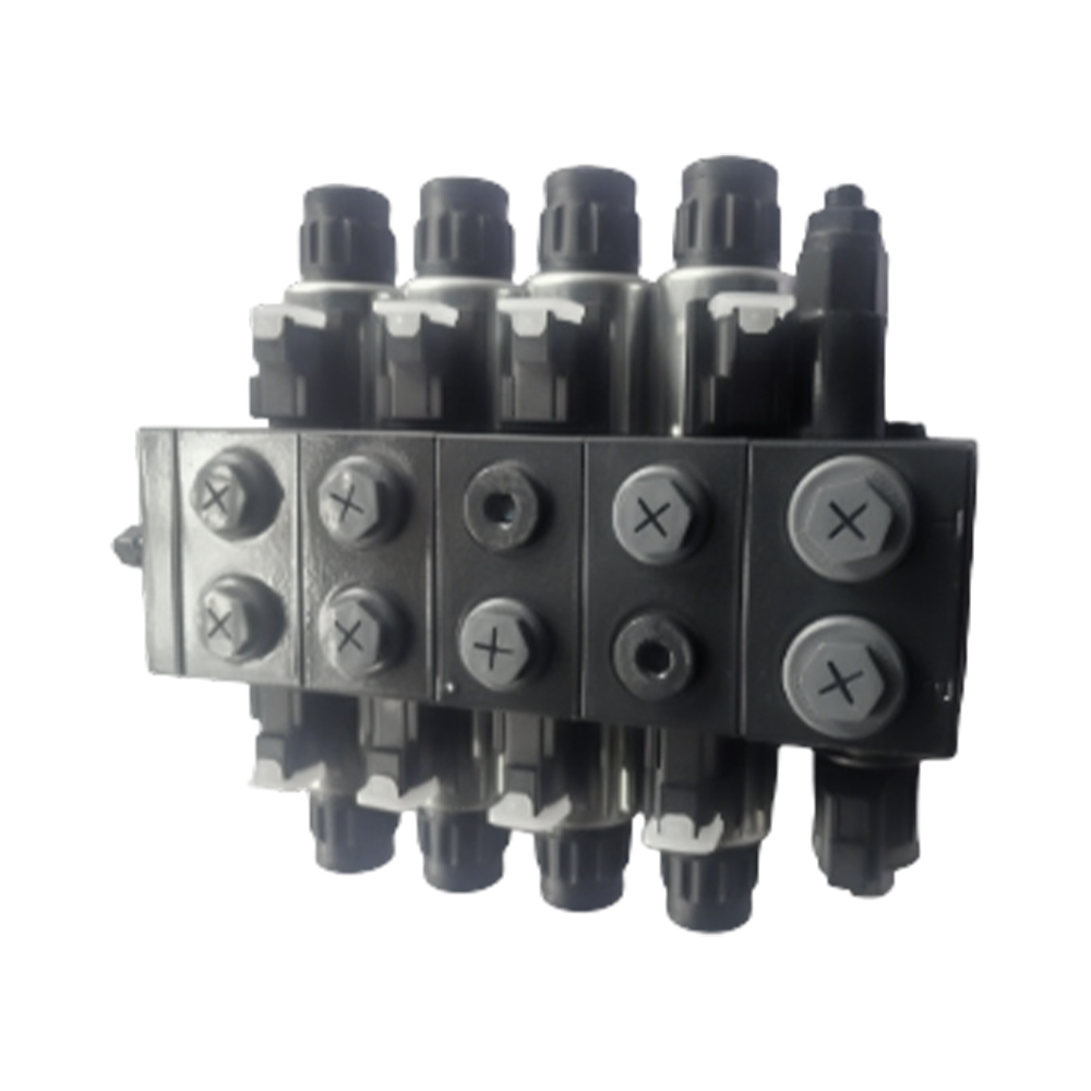
Sectional (Stackable) Design |
| Body Structure |
Cast as a single solid block. |
Individual valve slices bolted together. |
| Leakage Risk |
Lowest risk (no joints between sections). |
Higher risk at section interfaces (O-rings). |
| Flexibility |
Fixed number of spools (1 to 6). |
Highly customizable; sections can be added. |
| Maintenance |
If one bore fails, the whole block is replaced. |
Individual sections can be replaced or repaired. |
| Common Use |
Small tractors and compact industrial units. |
Large cranes, excavators, and complex rigs. |
4. Lever Linkage and Ergonomics
- Direct Linkage: The lever is pinned directly to the spool. This provides the most sensitive feedback, allowing the operator to feel the flow resistance.
- Joystick Control: A single handle can be linked to two separate spools via a universal joint. This allows for simultaneous control of two axes of movement (e.g., boom lift and bucket tilt) with one hand.
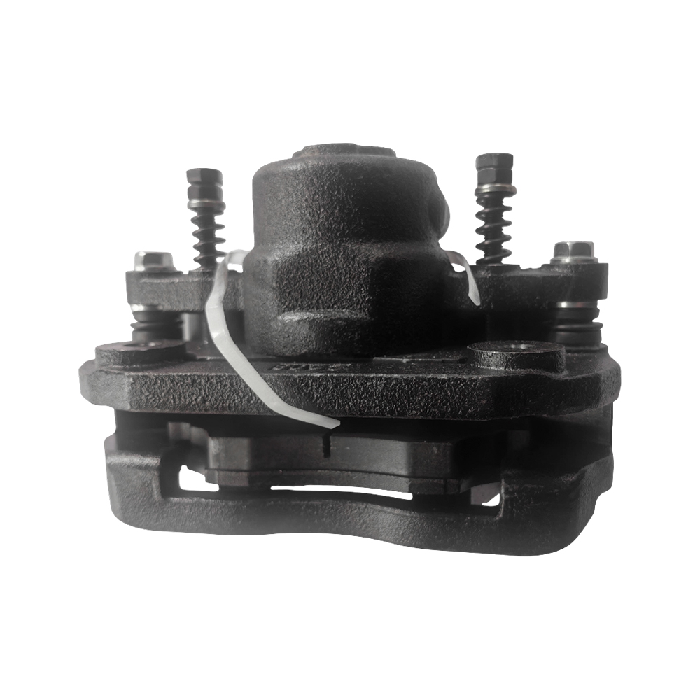
- Dust Boot Protection: Most high-quality manual valves feature a flexible rubber bellow (boot) at the lever base to prevent contaminants from entering the spool-bore interface, which is the leading cause of "sticky" valves.
Common Classification Methods
Manual directional valves are classified based on their functional logic and physical integration. Understanding these categories is essential for matching a valve to the specific dynamics of a hydraulic or pneumatic circuit.
1. Classification by "Way" and "Position."
The most fundamental way to categorize these valves is by the number of fluid ports (ways) and the number of distinct spool stop positions.
- Two-Way, Two-Position (2/2): Primarily used as a manual shut-off valve.
- Four-Way, Three-Position (4/3): The most common configuration for controlling double-acting cylinders. It provides forward, reverse, and neutral states.
- Four-Way, Two-Position (4/2): Used when a cylinder must always be in motion (either extended or retracted) without a stop state.
2. Classification by Center Function (Neutral Position)
The "Center Function" refers to how ports P (Pressure), T (Tank), A, and B (Actuators) are connected when the lever is in the middle neutral position. This choice dictates how the system behaves when idle.
| Center Type |
Port Connections |
System Behavior |
| Closed Center (O-Type) |
All ports (P, T, A, B)are blocked. |
Locks the actuator in place; maintains system pressure. |
| Open Center (H-Type) |
All ports are connected to the Tank. |
The motor or cylinder can "float" or be moved by hand; the pump pressure drops to zero. |
| Tandem Center (G-Type) |
P connected to T; A and B blocked. |
Unloads the pump to save energy while locking the actuator in position. |
| Float Center (Y-Type) |
P blocked; A and B connected to T. |
The actuator can move freely (float) while pressure is maintained for other valves. |
3. Classification by Mounting Style
The physical installation method impacts the footprint and ease of maintenance of the control block:
- Threaded (In-line) Mounting: The valve has threaded ports (e.g., NPT or BSPP) where hoses are connected directly. Ideal for simple, stand-alone applications.
- Sub-plate (Manifold) Mounting: The valve is bolted onto a machined plate. This allows for rapid replacement without disconnecting hoses, as all fluid paths are contained within the block.
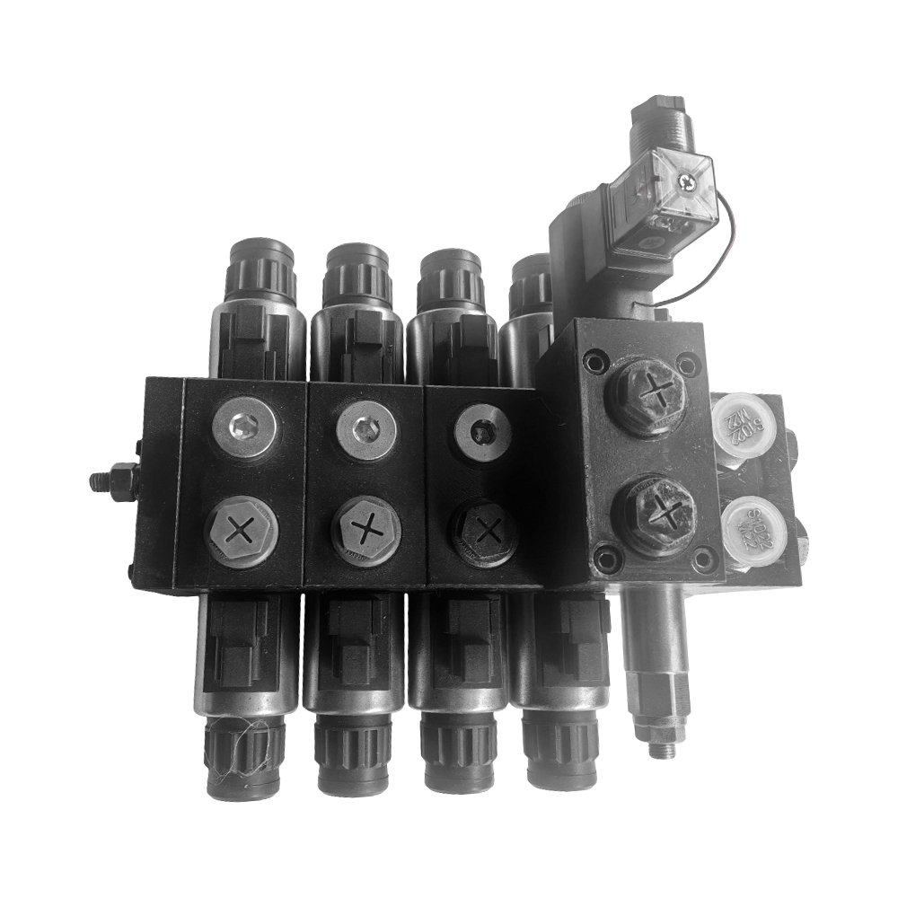
- Stackable (Monoblock/Sectional): As discussed in the construction section, these allow multiple valve units to be "stacked" together to control multiple functions from a single pressure source.
4. Classification by Actuation Style
- Hand Lever: The standard vertical or horizontal rod for manual gripping.
- Rotary Knob: Used for smaller valves where the operator twists a dial to change ports.
- Foot Pedal: A variation of manual control where the operator's foot provides the shifting force, freeing up hands for other tasks.
Key Selection Parameters
Selecting an inappropriate manual directional valve can lead to system overheating, sluggish actuator response, or even catastrophic component failure. To ensure peak performance, engineers must evaluate several critical performance metrics beyond simple port sizes.
1. Flow Rate and Pressure Drop
- Rated Flow: This is the maximum volume of fluid the valve can handle while maintaining an acceptable pressure drop. If the flow exceeds the valve’s rating, internal friction increases, leading to excessive heat generation and energy loss.
- Pressure Drop (ΔP): Every valve acts as a restriction. You must ensure that the pressure drop from the inlet (P) to the outlet (A or B) does not consume too much of the system's working pressure.
- Fluid Velocity: Higher flow rates in small valve bores increase fluid velocity, which can cause turbulence and cavitation, potentially damaging the internal spool surfaces.
2. Pressure Ratings
Manual valves are subject to three distinct pressure considerations:
- Nominal Pressure: The standard operating pressure for which the valve is designed.
- Maximum Intermittent Pressure: The peak pressure the valve can withstand for short bursts (e.g., during a sudden load spike).
- Tank Port (Backpressure) Rating: This is often overlooked. If the return line (T) has high backpressure, it can interfere with the spool movement or even blow out the spool seals. High-performance valves often have reinforced tank ports.
3. Parameter Selection Matrix
The following table serves as a quick-reference guide for aligning valve specifications with common application needs:
| Operating Condition |
Priority Parameter |
Recommended Specification |
| High-Precision Positioning |
Spool Metering/Stroke |
Select valves with metering notches on the spool for gradual flow control. |
| Continuous Heavy Lifting |
Duty Cycle & Cooling |
Higher flow rating than the pump output to minimize thermal buildup. |
| Extreme Cold Environment |
Seal Material |
Low-temperature Nitrile (NBR) or specialized Viton seals to prevent leakage. |
| Safety-Critical Static Loads |
Internal Leakage Rate |
Hardened steel spool with precision-honed fit (low cc/min leakage). |
4. Port Threads and Sizing
- Standardization: Ensure the port threads match your plumbing (e.g., SAE O-ring boss, BSPP, or NPT). SAE threads are often preferred in high-pressure hydraulic systems for their superior sealing at the threads.
- Over-sizing: It is generally better to slightly over-size a valve (e.g., using a 1/2" valve for a 3/8" line) to reduce flow resistance, provided the manual operating force remains manageable.
Typical Application Scenarios
Manual directional valves are favored in environments where simplicity, durability, and human intervention are prioritized. Their ability to provide fine-tuned control without complex electronics makes them the backbone of several critical industries.
1. Mobile and Engineering Machinery
In the mobile sector, manual valves are often grouped into "multi-way" blocks to control several functions simultaneously.
- Cranes and Lifting Equipment: Operators use manual levers to control the boom extension and winch speed. The tactile feedback allows them to feel if a load is swinging or if the system is approaching its pressure limit.
- Excavators and Backhoes: While many modern units use pilot control, manual overrides, or manual stabilizer leg controls are standard for their ruggedness against vibration and dirt.
- Recovery Vehicles: Tow trucks utilize manual valves to operate winches and tilt trays, providing the operator with direct control while standing at the side of the vehicle.
2. Agricultural Equipment
Agriculture requires equipment that can be repaired in the field with basic tools, making manual hydraulics the ideal choice.
- Tractor Implements: Controlling the height of a plow or the rotation of a seed spreader. These valves often feature a detent position to keep a motor running without the operator holding the handle.
- Log Splitters: A classic application for a single-spool manual valve with a pressure-actuated kick-out (automatically returning the handle to neutral when the cylinder reaches full stroke).
3. Industrial and Manufacturing Units
In factory settings, manual valves serve both operational and safety roles.
- Hydraulic Presses and Compactors: Manual control ensures that the operator's hands are engaged and that they have full control over the pressing speed during delicate assembly or waste baling.
- Workholding Fixtures: Manually clamping large parts in machining centers where a constant, non-electric hold is required for safety.
- Emergency Standby Systems: Many automated industrial power units (IPUs) include a manual directional valve as a backup bypass. If the electronic controller fails, a technician can manually shift the valve to safely retract cylinders or dump system pressure.
4. Application Logic Comparison
The following table illustrates how different application requirements dictate the specific valve configuration used:
| Application |
Primary Requirement |
Valve Configuration |
| Log Splitter |
Hands-free return |
Single-spool with Pressure Release Detent |
| Dump Truck Hoist |
Safety & Precision |
3-Way, 3-Position with Spring-to-Center |
| Forklift Mast |
Multi-axis control |
Sectional Valve Stack with tilt and lift spools |
| Scissor Lift |
Load holding |
Closed Center (O-Type) to prevent drifting |
Installation, Maintenance, and Troubleshooting
To maximize the lifespan of a Manual Directional Valve, proper installation and proactive maintenance are essential. Because these valves rely on high-precision internal clearances, they are particularly sensitive to fluid contamination and mechanical misalignment.
1. Installation Best Practices
- System Flushing: Before connecting the valve, flush the entire hydraulic or pneumatic system. Even microscopic metal shavings or assembly debris can score the spool and lead to permanent internal leakage.
- Port Identification: Always verify the P (Pressure), T (Tank/Return), and A/B (Work) ports. Connecting the pressure line to the tank port can result in seal failure or housing cracks due to excessive backpressure.
- Mounting Stress: Ensure the valve is mounted on a flat surface. If the mounting bolts are overtightened on an uneven surface, the valve body can slightly distort, causing the spool to bind or stick.
2. Routine Maintenance Procedures
A well-maintained manual valve can last for millions of cycles. Focus on these three areas:
- Fluid Cleanliness: Change filters regularly. Contaminated oil acts as an abrasive paste that widens the gap between the spool and the bore.
- Linkage Lubrication: Periodically apply grease to the external lever pivot pins and joints. This ensures smooth actuation and prevents the "notchy" feel that hinders precision control.
- Seal Inspection: Check the spool end seals (often O-rings or U-cups) for signs of weeping. Replacing a ten-cent seal early prevents a messy and hazardous workspace.
3. Troubleshooting Common Failures
When a manual valve malfunctions, the symptoms often point directly to the underlying mechanical cause:
| Symptom |
Probable Cause |
Recommended ActionThe handle |
| It is difficult to move |
Silt buildup or body distortion |
Check mounting torque; flush the system; check for a bent spool. |
| Actuator drifts (creeps) |
Internal bypass leakage |
Inspect the spool/bore for wear; check if the center function matches the load requirements. |
| Oil is leaking from the handle base |
Failed spool seal |
Replace the spool O-ring and check for dust boot damage. |
| The handle won't return to the center |
Broken return spring |
Disassemble the spring cap and replace the centering spring. |
| Excessive heat at the valve |
High pressure drop |
Confirm flow rate is within rated capacity; check for downstream obstructions. |
4. Conclusion
The manual directional valve remains a cornerstone of fluid power because it bridges the gap between human intent and mechanical force with simplicity and durability. By selecting the correct center function, respecting flow limits, and maintaining oil cleanliness, you ensure a control system that is both safe and efficient.
Summary Technical Specification & Final Inspection Checklist
To conclude this comprehensive guide, the following documentation serves as a final reference for engineers and technicians. These checklists ensure that the Manual Directional Valve is correctly specified before purchase and properly verified before the system is powered on.
1. Technical Specification Summary Sheet
Use these baseline values to verify if your selected valve meets the rigorous demands of your hydraulic or pneumatic circuit:
| Specification Item |
Standard Industrial Range |
Your System Requirement |
| Circuit Type |
Open Center / Closed Center / Tandem |
(Must match pump type) |
| Number of Spools |
1 to 10 Sections |
(Based on the number of actuators) |
| Max Operating Pressure |
250 Bar (3600 PSI) - 350 Bar (5000 PSI) |
(Should exceed relief valve setting) |
| Max Flow Rate |
40 L/min to 160 L/min |
(Check for ΔP at max flow) |
| Fluid Temperature |
-20°C to +80°C |
(Verify seal material compatibility) |
| Filtration Requirement |
ISO 4406 19/17/14 or better |
(Critical for spool longevity) |
2. Pre-Commissioning Inspection Checklist
Perform these checks before applying full system pressure to avoid mechanical damage or safety hazards:
- Mechanical Integrity:
- Check that the handle moves freely through all positions without binding.
- Ensure all mounting bolts are tightened to the manufacturer’s specified torque.
- Hydraulic Connections:
- Confirm that the Tank (T) line is unobstructed and leads directly to the reservoir.
- Check that all fittings are seated correctly to prevent high-pressure "pinhole" leaks.
- Safety Verification:
- If using a Spring-to-Center valve, verify that the handle snaps back to neutral immediately upon release.
- Ensure the operator’s area is clear of moving actuators during the first cycle.
- Environmental Protection:
- Confirm that the rubber dust boots are intact and properly seated to prevent ingress of dirt or moisture.
Final Summary
The Manual Directional Valve is a testament to the fact that mechanical simplicity often equates to operational reliability. By adhering to the principles of correct spool selection, pressure management, and clean installation, you ensure a control system that is both intuitive for the operator and durable for the machine.


 2026.02.11
  Industry News
 English
  Español