en
Need Help Now? Call Us!
+86-159 9623 5291

Our team proudly offers an on-time guarantee and a 100% customer satisfaction guarantee.
Contact Online


 Home / News / Industry News / Hydraulic Solenoid Directional Control Valve vs Manual Valve: A Complete Automation and Performance Comparison
  2026.06.21
  Industry News
 Content
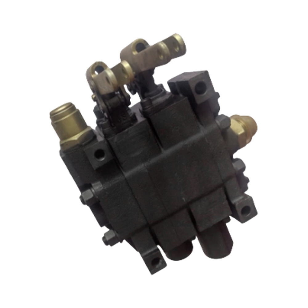
For hydraulic system designers, equipment manufacturers, and export sourcing professionals, selecting the correct directional control valve directly impacts machine automation capability, operator safety, and system responsiveness. Manual valves offer simplicity and direct tactile control but require operator presence at the valve location and cannot be integrated into automated control systems. Hydraulic Solenoid Directional Control Valves convert electrical signals into mechanical spool movement, enabling remote operation, programmable logic controller integration, and rapid response times that manual valves cannot match. Understanding the differences between these valve types helps buyers select the optimal solution for applications ranging from automated agricultural machinery to industrial production lines.
Manual valves rely on mechanical levers that the operator must physically move. This requires the operator to be near the valve, limits automation possibilities, and creates fatigue during repetitive operations. Solenoid valves use electromagnetic coils to shift the spool when electrical current is applied. This enables push button control from a remote operator station, automatic sequencing through programmable controllers, and response times measured in milliseconds rather than seconds. The following table summarizes the key differences between hydraulic solenoid directional control valves and manual valves.
| Performance Indicator | Hydraulic Solenoid Directional Control Valve | Manual Operated Valve |
|---|---|---|
| Control Method | Electrical signal from switch or controller | Mechanical lever operator hand movement |
| Operator Location Requirement | Remote any location with wiring | Must be within arm reach of valve |
| Automation Integration Capability | Full integration with PLC and computers | None direct manual only |
| Response Time | 20 to 80 milliseconds very fast | 0.5 to 2 seconds depends on operator |
| Multi Function Coordination | Excellent synchronized via control logic | Poor sequential operation requires multiple operators |
| Operator Fatigue in Repeated Cycles | None electrical switching only | High repetitive lever movement tiring |
Industry experience confirms that hydraulic solenoid directional control valves provide superior automation capability and operator comfort for applications involving frequent cycling or remote operation. For equipment that must function as part of an automated process, solenoid valve technology is essential rather than optional.
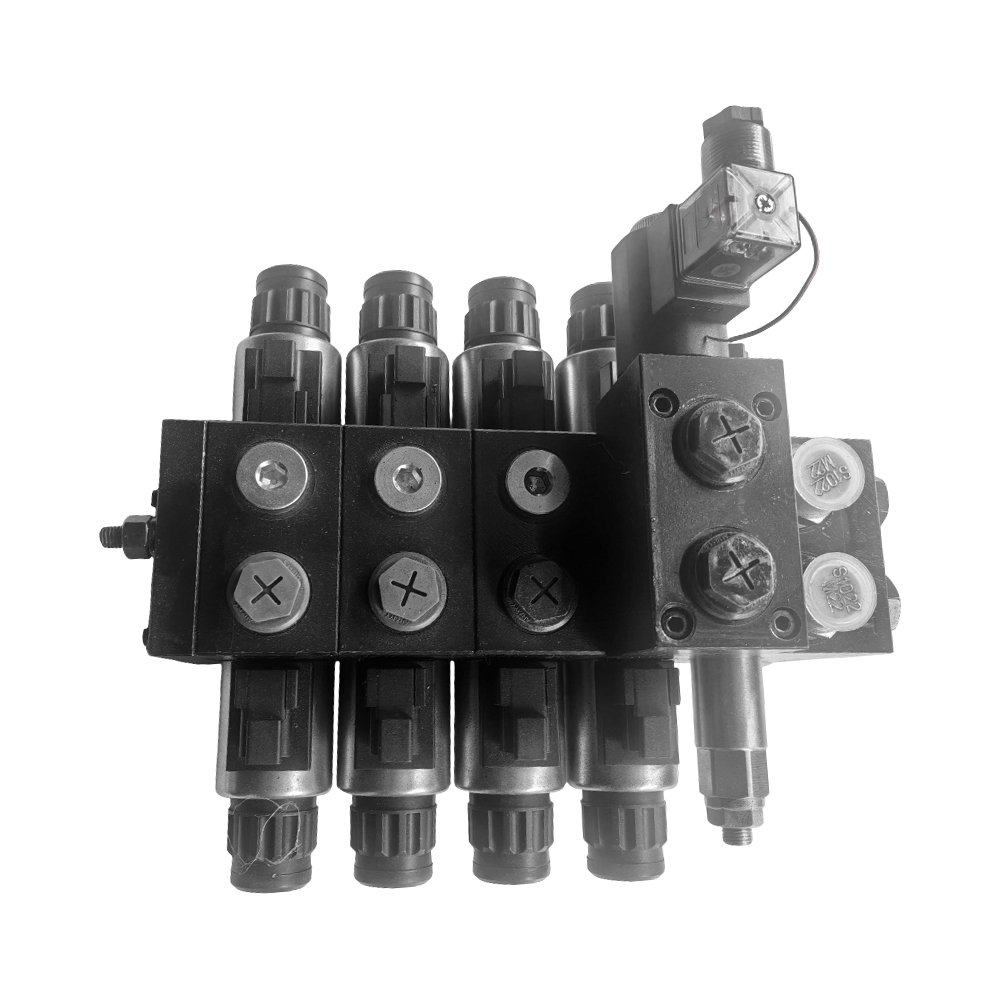
The Hydraulic Solenoid Directional Control Valve consists of several key components that work together to convert electrical signals into hydraulic flow control. Understanding this construction helps buyers evaluate valve quality and select appropriate configurations for their application.
The valve body is typically made from high strength cast iron or ductile iron that withstands hydraulic pressures up to 350 bar or 5000 pounds per square inch. The body contains precision machined bores that house the spool and provide flow passages between ports. Solenoid valves are available in two main construction types: wet armature and dry armature. Wet armature solenoids have the armature immersed in hydraulic fluid, which lubricates moving parts and dissipates heat but requires special attention to fluid cleanliness. Dry armature solenoids have the armature separated from the hydraulic fluid by a seal tube, keeping electrical components dry but creating additional friction. For most mobile and industrial applications, wet armature designs provide longer service life and higher force output.
The solenoid coil converts electrical energy into magnetic force that moves the armature and attached spool. Coils are rated by voltage, typically 12 or 24 volts DC for mobile applications and 110 or 220 volts AC for industrial applications. DC coils are quieter and generate less heat than AC coils but require adequate battery capacity. AC coils have higher inrush current for initial spool movement then lower holding current, providing strong shifting force with reduced heat during continuous operation. Coils are encapsulated to protect against moisture, dust, and vibration. Quality coils such as those used by Anhui Zhongjia Hydraulic Technology Co., Ltd. are tested for millions of cycles and rated for continuous operation without overheating.
The spool is the moving element that directs flow, identical in function to manual valve spools but shifted by solenoid force rather than lever movement. Spools are precision ground from hardened steel with surface finishes below 0.2 micrometers Ra. Different spool types provide different flow patterns, including open center, closed center, tandem center, float center, and regenerative center. Spool position is determined by which solenoid is energized. Two position valves have the spool at either end of travel. Three position valves have a spring centered neutral position with solenoids shifting the spool against spring force.
Manual override is an important feature on solenoid valves, allowing the valve to be shifted manually when electrical power is unavailable or during commissioning. A small button or lever on the solenoid housing pushes the armature and spool manually. Manual override is essential for troubleshooting and for emergency operation when electrical systems fail. Override mechanisms are typically spring returned and require tool or fingernail pressure to operate. For applications where the valve may need sustained manual operation, detented overrides that hold position without continuous pressure are available.
Hydraulic Solenoid Directional Control Valves are divided into two main categories based on how the solenoid force is applied to shift the spool. Understanding the difference between direct acting and pilot operated designs helps buyers select the right valve for their flow and pressure requirements.
Direct acting solenoid valves have the solenoid armature directly connected to the main spool. When the solenoid energizes, the armature pulls the spool directly to the shifted position. Direct acting valves are simple, reliable, and have the fastest response times, typically 20 to 40 milliseconds. However, the solenoid force required to shift the spool increases with flow and pressure because of hydraulic flow forces acting on the spool. Direct acting valves are therefore limited to smaller flows, typically up to 40 to 60 liters per minute. For low flow applications such as pilot circuits, brake systems, and small implements, direct acting valves provide excellent performance at lower cost.
Pilot operated solenoid valves use a small pilot solenoid to control the position of a larger main spool. When the pilot solenoid energizes, it directs a small amount of hydraulic fluid from the main pressure port to the end of the main spool, pushing the main spool to the shifted position. The pilot fluid then exhausts from the opposite end of the main spool back to tank. Pilot operated valves can control much higher flows than direct acting valves because the pilot system provides the force to move the main spool, not the solenoid directly. Flows from 80 to 300 liters per minute are typical for pilot operated valves. However, pilot operated valves require a minimum pressure, typically 5 to 10 bar, to generate the pilot force needed to shift the main spool. At very low pressures, the valve may not shift reliably. Pilot operated valves also have slightly slower response times than direct acting valves, typically 50 to 100 milliseconds.
Selecting between direct acting and pilot operated designs depends on the application. For low flow, low pressure systems where fast response is critical, direct acting valves are preferred. For high flow systems where pressure is available, pilot operated valves provide the necessary flow capacity with reasonable response time. For systems that must operate at very low pressure or that see frequent pressure decay, direct acting valves provide more reliable shifting. Many manufacturers including Anhui Zhongjia offer both types, allowing system designers to select the optimal valve for each function in a multi valve system.
Hydraulic Solenoid Directional Control Valves are available in several configurations that determine hydraulic circuit behavior. Understanding these configurations helps buyers select the right valve for their specific machine functions and control requirements.
Spool types determine flow paths in each spool position, identical to manual valves. Common spool types for solenoid valves include open center, closed center, tandem center, float center, and regenerative center. Open center spools connect all working ports to tank in neutral position, allowing pump flow to return to tank at low pressure. This is the most common configuration for open center hydraulic systems. Closed center spools block all ports in neutral, used with variable displacement pumps or accumulator circuits. Tandem center spools connect pump port to tank while blocking work ports in neutral, allowing actuator load holding while pump flow returns to tank. Float center spools connect both work ports to tank in neutral while blocking pump port, allowing the actuator to move freely under external forces.
Number of positions refers to how many discrete spool positions the valve provides. Two position valves have the spool at either end of travel, controlled by which solenoid is energized. Common two position configurations include spring offset where a spring returns the spool when the solenoid is de energized, and detented where the spool stays in position after the solenoid de energizes until the opposite solenoid energizes. Three position valves have a spring centered neutral position with solenoids on each end shifting the spool against spring force. When both solenoids are de energized, springs return the spool to center. Three position valves are the most common for bi directional actuator control such as extending and retracting a cylinder.
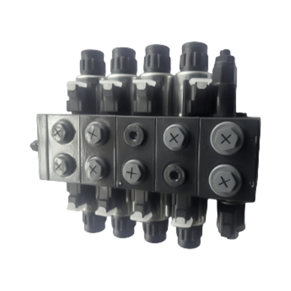
Number of ways refers to how many flow paths the valve can connect. Four way three position valves are the most common, with pressure port, tank port, and two work ports. Four way valves control bi directional cylinders and motors. Three way valves are used for single acting cylinders, with pressure, tank, and one work port. Two way valves are used as simple on off switches for hydraulic circuits. For complex multi actuator systems, multi section solenoid valve banks integrate multiple spools into a single assembly, reducing space and piping complexity.
Voltage options include 12 volts DC for most mobile equipment, 24 volts DC for larger mobile machinery and industrial applications, and 110 or 220 volts AC for stationary industrial equipment. DC coils are preferred for mobile applications because they operate from the vehicle battery and are less sensitive to voltage drop. AC coils provide higher inrush current for positive shifting but can burn out if the spool sticks, requiring careful attention to fluid cleanliness. For export applications, verify voltage compatibility with the destination market's standard electrical systems before ordering.
Proper electrical connection is essential for reliable solenoid valve operation. Various connection options are available to suit different environmental conditions and control system requirements. Understanding these options helps buyers select valves that integrate seamlessly with their equipment.
DIN connectors are the industry standard for solenoid valve electrical connections. The DIN 43650 form A connector is a rectangular 3 pin connector that provides IP65 protection against dust and water jets when properly mated. The connector includes a ground terminal for safety. DIN connectors are preferred for industrial and mobile applications because they are widely available, provide secure locking, and allow quick replacement of the coil without rewiring. For wet or wash down environments, IP67 or IP69K rated connectors are available with additional sealing.
Lead wires are a lower cost alternative to DIN connectors, with the coil having permanently attached wires that exit through a strain relief. Lead wires are less convenient for replacement but may be acceptable for applications where the valve is not frequently removed. Lead wires are typically 300 to 500 millimeters long and are available in a range of wire gauges. For high vibration applications, lead wires with additional strain relief are recommended.
Plug and receptacle connections provide the highest level of environmental protection and are commonly used on mobile equipment that sees high pressure wash down. Deutsch and AMP type connectors provide sealed connections that withstand high pressure spray and salt exposure. These connectors are more expensive than DIN connectors but provide greater reliability in harsh conditions. For export equipment used in marine or agricultural environments, Deutsch connectors are often specified.
Indicator lights are available on some solenoid coils to show when the coil is energized. These lights help operators and maintenance technicians verify that electrical power is reaching the valve. LED indicators have long life and low power consumption. Some indicator lights are built into the DIN connector, while others are integrated into the coil molding. For troubleshooting in the field, valves with indicator lights reduce diagnostic time significantly.
Different industries and applications require specific Hydraulic Solenoid Directional Control Valve configurations. Understanding these requirements helps buyers select the correct valve specifications for their equipment and operating conditions.
For agricultural machinery including tractors, combines, and sprayers, solenoid valves enable automated functions that improve productivity. Typical applications include header height control, reel speed control, and automatic steering. Valves must withstand outdoor exposure to dust, mud, moisture, and temperature extremes. DIN connectors with IP67 rating provide adequate protection for most agricultural applications. For the highest reliability, valves with manual override allow continued operation if electrical systems fail. Flow rates typically range from 30 to 150 liters per minute at pressures up to 250 bar. For precision agriculture applications, valves with proportional control capability provide fine metering for implement control.
For industrial machinery including presses, injection molding machines, and material handling equipment, solenoid valves are integrated into automated production lines. Valves are typically mounted on manifolds to reduce piping and leak points. AC coils are common because of the availability of industrial power. For noise sensitive environments, valves with special silencing features reduce pilot exhaust noise. Flow rates range from 20 to 300 liters per minute at pressures up to 350 bar. For high cycle applications, valves with extended life coils and hardened spools are specified.
For mobile construction equipment including excavators, loaders, and cranes, solenoid valves enable remote control of auxiliary functions. Pilot operated valves are common because of the high flows required for hydraulic motors and cylinders. Valves must withstand vibration and shock loading. Weather sealed connectors and corrosion resistant bodies are essential. For excavator attachments such as thumbs and compactors, solenoid valves mounted directly on the attachment provide convenient control from the cab. Flow rates range from 60 to 200 liters per minute at pressures up to 300 bar.
For material handling equipment including forklifts and aerial lifts, solenoid valves enhance safety through automatic functions. Typical applications include automatic leveling, speed limiting, and load holding. Valves with integrated pilot operated check valves prevent load drift when the spool is in neutral. For electric forklifts, low power consumption coils extend battery life. Flow rates typically range from 15 to 60 liters per minute at pressures up to 210 bar. For aerial lifts, valves with emergency lowering capability provide safety during power failure.
What is the typical operating life of a hydraulic solenoid directional control valve?
With proper installation and clean hydraulic fluid, a quality solenoid directional control valve can achieve 5 to 10 million cycles or more before solenoid coil failure or spool wear. The solenoid coil is typically the life limiting component, with failure rates increasing after 5 million cycles due to insulation breakdown from heat and voltage spikes. Spool and body wear is minimal with proper fluid cleanliness of ISO 16 13 or better. For high cycle applications such as injection molding machines, specify valves with extended life coils rated for 10 to 20 million cycles. Manufacturers such as Anhui Zhongjia Hydraulic Technology Co., Ltd. perform cycle testing to validate life ratings.
Can solenoid valves be used in outdoor or wash down environments?
Yes, with appropriate environmental protection. Solenoid valves with IP67 rated connectors and coils provide protection against temporary immersion and high pressure spray. For continuous outdoor exposure, additional protection such as a valve cover or enclosure is recommended. The valve body itself is typically cast iron or steel and resists corrosion when properly coated. However, the solenoid coil housing and electrical connections are the vulnerable points. For marine environments or applications with salt exposure, specify valves with stainless steel components and special corrosion resistant coatings. For food processing wash down applications, stainless steel bodied valves with smooth surfaces for cleaning are available.
What is the difference between a 2 position and 3 position solenoid valve?
A 2 position solenoid valve has the spool at either end of its travel, with no spring centered neutral position. When one solenoid energizes, the spool shifts to that position and stays there until the opposite solenoid energizes or until the spool is manually centered. Two position valves are used for simple on off applications such as clutch engagement or brake application. A 3 position solenoid valve has a spring centered neutral position with solenoids on each end shifting the spool against spring force. When both solenoids are de energized, springs return the spool to center. Three position valves are used for bi directional cylinder and motor control, with the center position typically being pump unload, load hold, or float.
Why is my solenoid valve not shifting when I apply power?
Several common issues can prevent solenoid valve shifting. First, verify that correct voltage is reaching the coil using a voltmeter. Low voltage from weak batteries or undersized wiring is a common cause. Second, check the coil resistance with an ohmmeter; a reading of infinity indicates an open coil, while a reading significantly below specification indicates a short. Third, verify that system pressure is above the minimum required for pilot operated valves, typically 5 to 10 bar. Fourth, check for contamination that could be holding the spool. Fifth, verify manual override operation; if the valve shifts manually but not electrically, the issue is electrical. If the valve does not shift manually, the issue is mechanical or hydraulic.
What is the typical minimum order quantity for custom hydraulic solenoid directional control valves?
Minimum order quantities for custom hydraulic solenoid directional control valves vary by manufacturer and specification complexity. For simple customizations such as specific spool types, spring rates, or manual override styles on standard valve bodies, manufacturers typically require 50 to 100 pieces per configuration. For fully custom valves requiring new casting tooling or special port locations, minimum orders of 500 to 1,000 pieces are typical. Custom coil voltages or special connector configurations may have lower minimums because coils are produced separately from the valve body. Lead times for custom valves range from 60 to 120 days depending on tooling requirements. For smaller quantities, consider standard valves with available options or valves from stock with custom labels or packaging.
1. ISO 4401:2020. Hydraulic fluid power - Four-port directional control valves - Mounting surfaces. International Organization for Standardization.
2. ISO 9461:2020. Hydraulic fluid power - Marking of directional control valves. International Organization for Standardization.
3. NFPA T3.5.1-2019. Hydraulic fluid power - Directional control valves - Methods for testing. National Fluid Power Association.
4. IEC 60947-5-2:2020. Low-voltage switchgear and controlgear - Part 5-2: Control circuit devices and switching elements - Proximity switches. International Electrotechnical Commission.
5. SAE International. (2021). SAE J1534: Specification for Hydraulic Directional Control Valves. SAE International.
Recommended Products

Contact Info.
+86-159 9623 5291
No. 5, Chuangye Road, Niandou Industrial Park, Ma'anshan City, Anhui Province, China
MOBILE QR CODE
 English
  Español